Refers to the MAX7219 chip, a multiplexing LED driver. Use this tag for discussing the MAX7219 chip.
The MAX7219 chip is designed to drive an 8x8 LED display quite simply. It automatically and rapidly turns on display segments by progressively activating a row in the display, with a certain pattern for each column. It then moves onto the next row, repeating rapidly so that all of the rows and columns appear to be on at once (or at least, as many as are wanted).
The rows are activated at around 800 Hz, which provides a flicker-free display. The output is also current-limited, avoiding the need for current-limiting resistors for the LEDs. The actual current is set by a single "current-set" resistor.
Suitable displays
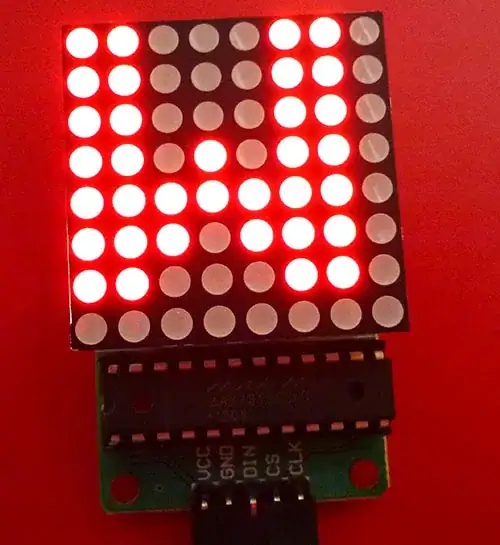
Typically two different sorts of displays can be driven. One is an 8x8 "matrix" like this:
The MAX7219 chip is visible in the above photo, below the LED matrix.
The second type is a 7-segment display (the 8th row being the decimal place) like this:
In this case the MAX7219 chip is mounted on the back of the circuit board.
Communication
The Arduino controls the MAX7219 by using SPI, or just shifting bits out.
Data is sent using the following signals:
- MOSI (Master Out, Slave In) from the Arduino to the Din (Data In) pin
- SCK (Serial Clock) from the Arduino to the CLK (clock) pin
- SS (Slave Select) from the Arduino to the LOAD pin
- +5 V
- Gnd
Interfacing with the 7-segment displays is easy, because the MAX7219 has inbuilt patterns for the standard digits (0-9, plus a few others like "H", "E", "L", "P", space, and "-") - that is, 16 standard characters. You can choose to use your own patterns if you want to display things like hexadecimal numbers.
To drive the 8x8 matrix a program would typically include a 8x8 font in the form of a table of appropriate bit patterns, usually stored in PROGMEM to save wasting RAM.
Daisy-chaining
The chip also has a Dout pin (data out), so that multiple chips can be daisy-chained. If more than 8 bits are clocked in, they start appearing on the Dout pin, which can be connected to the Din (data in) pin if the next chip in the chain.
In this way multiple displays can be connected up, making it possible to display whole sentences. For example:


