-1

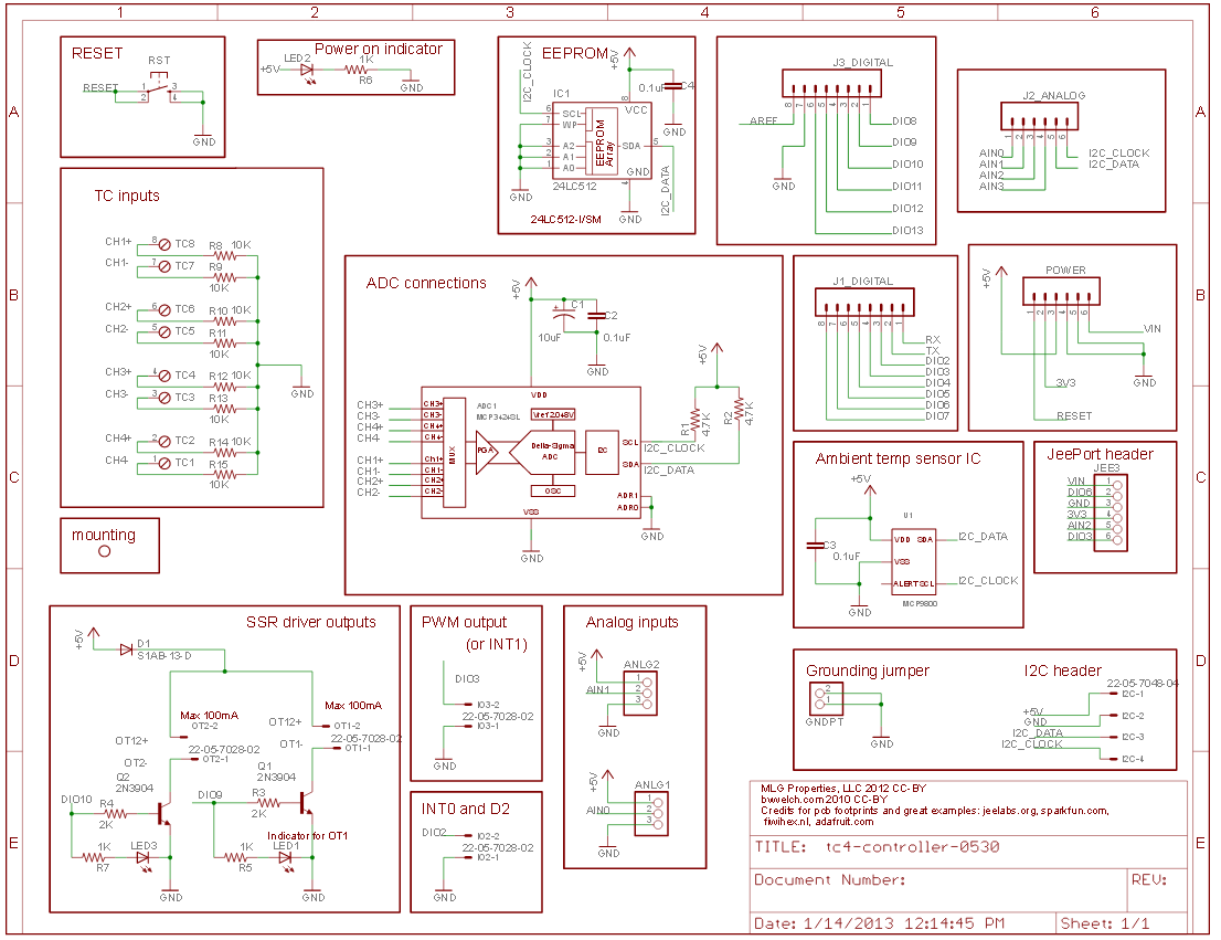
I am using the circuit below for reading analog values.

I wanted to measure 0-10 V DC and 0-30 V DC. I wanted to use it in applications where accuracy important.

ADC Schematic diagram

If I wanted to 12/16 bit resolution of value weather above circuit work out.

Channel-1+ & channel - should be given in range of 0-5 V through voltage divider network:

Vout=(Vs*R2)(R1+R2) -> R1=R2=1K Vs=0-10 V from DC output/sensor

If it is 0-30 V DC

Vout=(Vs*R2)(R1+R2) -> R1=5K R2=10K Vs=0-30 V from DC output/sensor

Is it correct?

Using voltage divider network we can measure voltage. But how can measure using MCP series module? Is there any proven schematic to test it out?

Greenonline
  • 2,969
  • 5
  • 27
  • 38
Ajit N
  • 37
  • 2
  • 5

2 Answers2

0

The circuit you show appears to be using I²C. However this shows pullup to 5V!

Connecting GPIO to 5V will destroy the Pi!

You can drive I²C from the Pi; it includes on-board pullup, so NO EXTERNAL PULLUP are needed. If they are present they NEED to be removed.

The resistors R1, R2 have NOTHING to do with a voltage divider. You will need to supply your own circuitry.

No idea what the block in the bottom RH corner is supposed to be.

Milliways
  • 62,573
  • 32
  • 113
  • 225
0

Question

  1. MCP3424 ADC 0~10VDC, 0~30 VDC, 12/16 bit resolution

  2. Sensor Output Divider - 10V x 1k/(1k + 1k) = 5V, 30V x 5k/(5k + 10K) = 5V OK?

Answer

  1. No problem at all. You can even do 18 bit resolution.

  2. Using resistive voltage divider might not be a good idea, especially if you want high resolution. Perhaps you should consider a high impedance OpAmp instead of simple resistor divider. MCP3424 full scale input is -2.04V to +2.04v, not 0~5V. So your resistor values might not apply.

References

MCP3424 ADC-4 Digital I2C Channel Conversion Module for Raspberry Pi for Arduino 2.7-5.5 V High Precision - US$4

MCP3424 Schematic

MCP3424 Datasheet - Microchip

ADS1256 SPI 24 bit ΔΣ ADC Engineering Experimention Notes - tlfong01

Sending I2C-bus signals via long communications cables AN10658 — NXP 2008feb26

I2C Cable Length and Type - Rpi StckExch Discussions

MCP3008 Analog Input Resistive Voltage Divider Discussion - Rpi StackExchange

OpAmp Input Voltage Divider Discussion - Electronics Stack Exchange

Appendices

Appendix A - MCP3424 Summary

Four Differential Channels

Two conversion modes - One-Shot mode, Continuous mode

Auto-calibration internal offset and gain each conversion

Programmable Gain Amplifier x 1, x 2, x 4, x 8 (error: 0.05%)

On board 2.048V reference - Full-range - 2.048V ~ +2.048V

Programmable Resolution: 12, 14, 16, 18 bits

Programmable data rate: 3.75 ~ 240 sps

Appendix B - GY-MCP3424 Module

gy-mcp3424 module

Appendix C - MCP3424 Module Schematic

mcp3424 schematic

Appendix D - MCP3424 Analog Input Block Diagram

mcp3424 analog input

tlfong01
  • 4,847
  • 3
  • 12
  • 24