Question
Setup = Many many RPi's, relays, sensors powered by many many [5V, 10A] PSUs
OK to connect all the PSUs together at the Negative [Ground] terminal negative ('-')?
Sufficient for the RPIs controlling relay and sensors?
Still need connect all Rpi's [signal] GNDs to the PSU ground's
Does any "end" of it require any other components to make it safe/safer?
Or better connect the RPis GND's to the actual [mains 200VAC] earth ground?
Difference between [200VAC mains] earth ground and RPI ground pins
Understanding this 1 would probably allow me to answer myself all the previous questions. Maybe.
Answers
So you have a long list of questions. Let me start at the end, Q8 + Q7.
Difference between [200VAC mains] earth ground and RPI ground pins
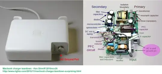
As I understand, all wall warts (except perhaps the very expensive Apple ones) do not ground to the mains ground, because they have insulated plastic covers and would not leak electricity (so as the bubble gum vendor say), though I often heard from news, up north of my city, that some 10 mobile users got killed by electricity leaking fake USB chargers every year. Nowadays it is no loner "news", so I don't hear those news and have lost count now. But I do remember not to long ago Samsung 7 chargers explode. But like all huge SamSung fans, I have a very short memory, and still renewing my Samsung handset every one or two years.
Though I don't earth ground my floating PSU, I always ground the casing, as described in the following answer:
How to ground your floating PSU and 200VAC mains output relay modules
Does any "end" of it require any other components to make it
safe/safer?
It is not clear what do you mean by "safer". Does it mean less EMI floating around and cause your old cat an heart attack? Or safer because EMI won't attack your Rpi and cause it intermittently self reboot? There are 101 ways to make you thing "safer". For the EMI thing, you might like to add a "snubber". See below.
Using Snubbers to suppress EMI

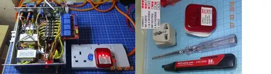
And to play safe, you can use electricity leakage protect circuit breaking plugs.
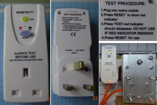
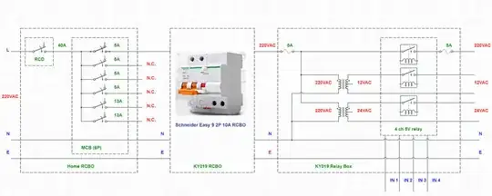
RCBO for outdoor 200VAC mains
And if your 200VAC mains extends to outdoor, like my rooftop garden, you may consider installing a 200VAC 10A RCBO for all the relay modules, as show below.
I am planning to use DC12V for relays and motors, DC24V for home appliances such as desk lamps. I avoid using relays to control 200VAC for safety reasons. On the other hand 12/24VDC is optimum. DC24V wall warts are common of home desk lamps. One way is to borrow the DC24V to supply the Songle 24V based relay modules (still 5V control signal though). This is a bit complicated. Perhaps I could show more pictures later, ...
Still need connect all Rpi's [signal] GNDs to the PSU ground's?
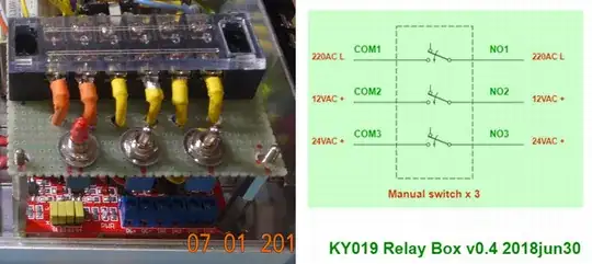
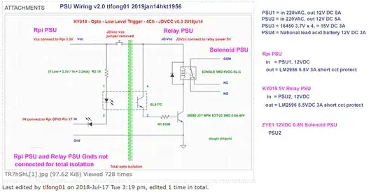
Well, if you browse the EE StackExchange, the EE guys would tell you that home mains 220VAC grounding is the mother of all noises. In other words, all noise bad guys, no mater back EMF or EMI (actually boils down to the same thing, according to the Scottish guy Maxwell and his huge fan Heaviside)) travels through the connecting wires (or more precisely, on the skin of the wires). So using the relay as an example, I almost never connect Rpi's signal ground to the relay's Songle relay switch 5/12/24VDC power ground. I only communicate/talkrol through light/optical (OK, still electromagnetic waves) signal to the Songle guys. In other words,
TOTAL OPTICAL ISOLATION, NO COMMON ELECTRICAL GROUND, as shown below.
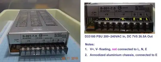
many many [5V, 10A] PSUs
So we have scratched the surface of the 200VAC mains / 5V DC PSU grounding problem. Now let us jump to the beginning of your quesions list, the 5V, 10A PSUs.
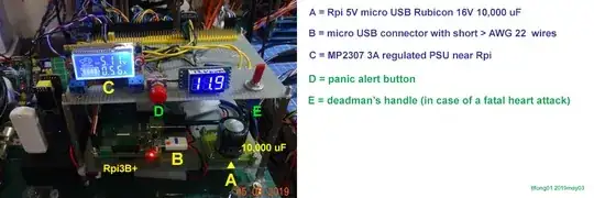
There are many styles of distributing PSUs. I have 4 Rpi3B+, and I have 4 12V in 5V out, 3A+ PSUs, each of which is dedicated to one and only one Rpi. You may like to read my answer to the following post to get a rough idea of how I treated my Rpi like a VIP, with dedicated PSU, private bath rooms, etc,... :)
Dedicated PSU (with 10,000 uF by pass cap) for VIP Rpi
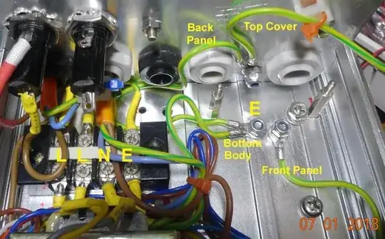
Earth stud example
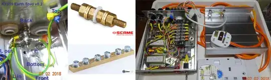
The relay box has an earth stud where the earth wires of all 6 anodized aluminium plates go to, forming a single earth point. This earth thing is for safety, so that any loosen dangling main live wire touching the chassis will not cause any harm to the human body touching the chassis, because almost all leaking electricity will pass through the earth wire to live wire to plug, to socket, to home mains MCB, and in my case, to the 28 story flats down to the real earth stud buried at the basement of the building (This is what I read and educated guess, I have not seen the real earth stud!) The AC 12V/24V transformers are floating, not touching the metal chassis or the quad relay board.
Update 2019may11hkt1212
200VAC Mains Earth vs 6~30VDC PSU Power Ground vs Logic Circuit Signal Ground
I usually distinguish among three earth/grounds by colours and AWG.
Main Earth - Green, thickest (standard 15A mains wire), connected to plug's earth wire, etc
PSU Ground - Black, thick (AWG 22+)
Logic Ground - Grey, thin (AWG 26~30)
I usually use a tree/hierarchical grounding configuration, not a star, never a ring. And PSU ground is never connected to mains earth. I know many industrial/academic labs have their PSU ground connected to main earth to illuminate all mains noise. But I never did that. Perhaps you can google and convenience me that it is a good idea.