7

According to the answer to Where is the USB2 OTG port on the RPi 4 Model B located? the Raspberry Pi 4B has a "hidden" OTG port in the USB-C power connector. I found at Very simple OTG on pi4 and at 4 ways to connect your Raspberry Pi 4 to the internet how to use the USB2 OTG port just with a simple USB cord. But this is very unstable because the USB port on the connected laptop cannot provide enough power (2.5A - 3.0A).

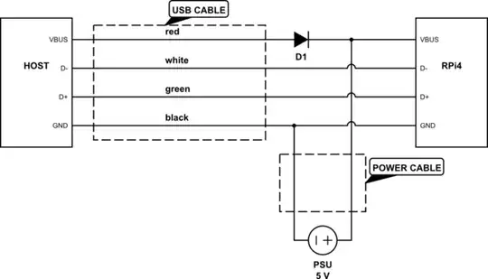
My first idea to use this port was to power the RasPi through the +pin and GND pin on the GPIO pins to use the OTG port. But I don't want to bypass the polyfuse on the USB-C power connector. I also do not have a POE (power over ethernet) HAT to power the pi this way. So I'm looking for an Y splitter cable for this port so I can power the RasPi with the power supply but also can use the OTG port.

Is it possible to make such an Y splitter cable? If so, how to make it? Or is there a better alternative? A simple drawing would be nice.

Ingo
  • 42,961
  • 20
  • 87
  • 207

2 Answers2

7

The problem here is that the RPi 4 USB-C connector is hard-wired as an upstream-facing port, which urges the host device on the other side to provide power. Yet if you power the RPi from an independent power supply (using an Y-cable or via the 5V pin), this supply will be connected in parallel to the host device's 5V output, which is problematic.

The simplest solution would be to make a cable which only conveys USB data signals (and ground) but not 5V. However, such a cable wouldn't behave in strict compliance with USB if plugged into an unpowered RPi, because signals on D+/D- lines may then have higher voltage levels that VBUS. Personally I'd add a diode feeding some voltage from host to the RPi (which, as you said, won't likely be enough to power the RPi anyway), just to cover this case. Here's how an Y-cable could look like:

schematic

simulate this circuit – Schematic created using CircuitLab

You still shouldn't plug the cable in the RPi while the PSU is off, because that would result in the overcurrent on the host USB port, but at least that won't damage the RPi. If you're careful about always plugging the PSU first, you could omit the diode (leaving VBUS line disconnected).

The power cable could also be connected to 5V/GND pins on the GPIO connector, which will correspond to the same circuit when the USB-C connector is plugged in.

Dmitry Grigoryev
  • 28,277
  • 6
  • 54
  • 147
2

Seamus is right mentioning the significant voltage drop across that diode. If you are concerned regarding D+ or D- getting a higher voltage than VBUS (which might indeed lead to a destructive effect called "latch-up"), I would recommend to use Schottky diodes (like Seamus suggested), but connect them like shown in this crude schematic:

schematic

simulate this circuit – Schematic created using CircuitLab

Midi
  • 29
  • 1