I am currently trying to learn about SPI and how it works on the Arduino. I want to wire a MAX7219 chip to it to drive an 8x8 LED matrix with. Normally, I would assume the wiring from Arduino to MAX7219 goes:
- PIN 10 SS -> CS
- PIN 11 MOSI -> DIN
- PIN 13 SCK -> CLK
And indeed, this answer confirms my assumption. However, after going through some other resources and guides I found some confusing and conflicting information about how the pins on the two devices should be connected.
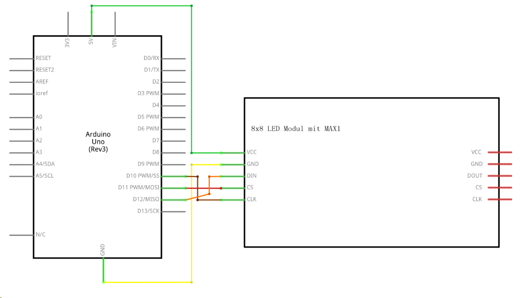
For instance, the documentation that came with my Arduino kit has this schematic.
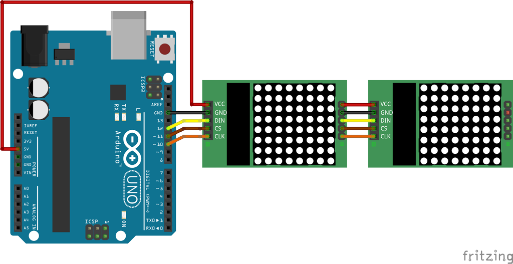
This tutorial I found has the same wiring.
Most surprisingly, this tutorial doesn't even use the SPI pins at all.
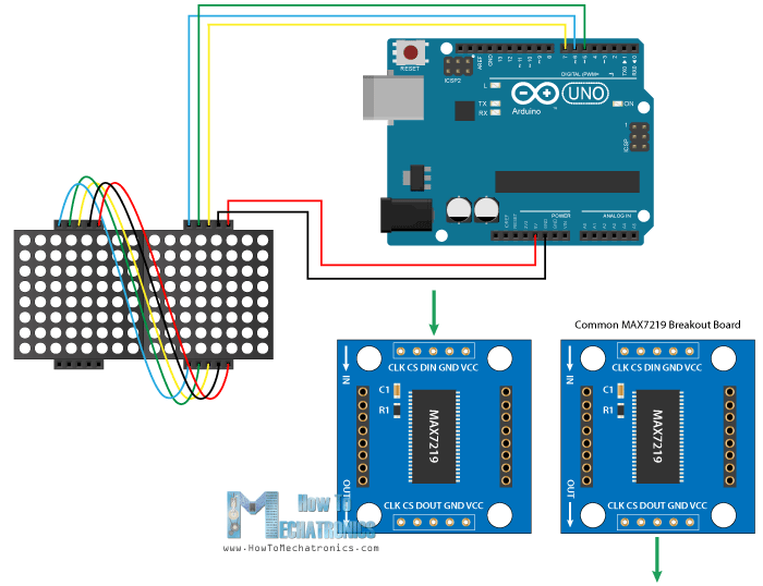
What perplexes me the most is the sentence
The VCC and GND of the module go to the 5V and GND pins of the Arduino and the three other pins, DIN, CLK and CS go to any digital pin of the Arduino board.
Is this true? If yes, then what is the point of the SPI pins at all? Why are the pins wired in so many different configurations? I am really confused by this.