Introduction
I found OP's "GPIO pin Low not Low enough" question very interesting.
I agree with Jaromanda X in chat saying:
... relay triggers on LOW not on HIGH ... when ... LOW, it should be in it's triggered state ... so that may be why you think GPIO21 being LOW is not doing what you want!
In other words, OP seems to have asked the wrong question. Instead OP should ask:
Why Rpi Low can switch on relay but Rpi High cannot switch off. Is Rpi High not High Enough?
I browsed SE and found a similar FAQ:
*Rpi Low can switch on relay, but High cannot switch off, ... *
Rpi cannot switch off, though I can switch off by GPIO.cleanukp, ...
The FAQ's answer is the following get around:
Don't use Rpi High to switch off, instead Set GPIO to Input.
*A similar trick to GPIO.cleanup, which resets GPIO to Input"
Everybody says this trick works, but nobody explains why it works.
And there is a big problem with this set-gpio-to-input-mode-to-turn-off-relay is that you cannot initialize you system with relay off. Whenever you say something like below:
GPIO.setup(11, GPIO.OUT, inital = GPIO.HIGH)
Your system is initialized with GPIO pin high, but relay is already on.
Anyway, I was curious to know why the trick works, and more importantly if it damages or shorten Rpi's life. And if there is a better way to turn off relay. So I did some experiments and summarized the results and conclusion below.
Op's module spec
OP's module is 5V Low Level Trigger One 1 Channel Relay Module DC AC 220V Interface Relay Board Shield LED Indicator for Arduino
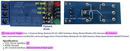

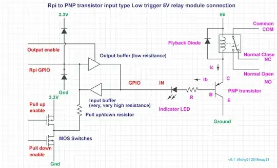
I agree Millways saying in chat that it should be PNP transistor input module:
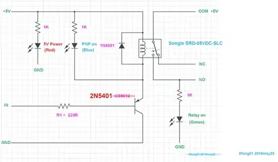
I guess the circuit is something like below:
Now I am trying to vary the IN to transistor base resistance from 220R to a higher value, hoping that now even Rpi GPIO High of 2.4V is high enough to turn off the relay.
However, I very soon found OP's relay module spec a bit unusual. It says drive current at least 4mA Ib, to switch on PNP BJT Ic to drive the 55R coil at 90mA. This implies a DC current gain of 90/4 ~= 20.
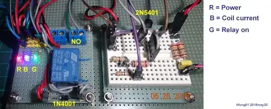
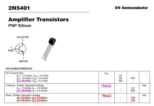
I found my first PNP to simulate OP's module is not suitable, because the Ic(sat) too big. So I replaced it by 2N5401 (see appendix below for a spec summary), which at Ib = 1mA, Ic = 50mA, hFE already is 50.
In other words, this 2N5401 module input current of 1mA, 1/4 of OP's module, is enough to switch on the relay. So I cannot simulate OP's module of 4mA input, 2.4V+ relay switch off condition.
Instead, I just tried to bias the PNP BJT to trigger at 1.0V+, which is high enough to entertain RPi's 0.6V- Low. And the trigger/activate deactivate band is around 0.2V-. I repeatedly verify that the trigger signal 0.2V to 1.0V will activate the relay and 1.0V to 2.4V (rpi's high
So Rpi's High of 2.4V+ must be able to switch the relay off!.
After manually tested the module using a 0~5V power supply unit to simulate Rpi/Arduino GPIO signals and found everything working as expected, the time has come to do the real thing: actually using Rpi GPIO signal instead of the 0~5v PSU, using an working python program.
But to my surprise, the program does NOT work!
The reason is that I forgot there is something called hysteresis. The relay switch hysteresis characteristic is as below.

/ to be continued, ...
Why the set-GPIO-to-input trick can switch relay off
/ to be continued, ...
Appendices
2N5401 hFE, Ib, Ic, Vce(sat), Vbe(sat)

.END


