8

This seems like it should be really simple, so maybe I am missing something. I am just trying to open and close my relay but all it does it open's and doesnt close. I can use GPIO.cleanup() to make it close but I dont want to apply this at this point in the project.

Link to 5v relay -> https://www.amazon.co.uk/XCSOURCE-Channel-optocoupler-Arduino-TE213/dp/B00ZR3B252

UPDATE: 6th Jan 17 As suggested in the comments I have tested the GPIO's and can see that 3.3V comes out when HIGH and it goes back to 0v on LOW. But LOW does not turn off the relay oddly. I have tried 2 of these relays and both do not switch off when at LOW (0v).

I have tried to find the original documentation for GPIO.clean() function since this allows it to close but cant find it. Can anyone think why this does this?

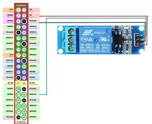
enter image description here

import RPi.GPIO as GPIO
from time import sleep

relayPin = 32

GPIO.setmode(GPIO.BOARD)
GPIO.setup(relayPin, GPIO.OUT)

## Turn on the Relay (this works - it clicks gives 3.3v)
GPIO.output(relayPin,GPIO.HIGH)
sleep(1)

## Turn off the Relay (this does nothing but goes back to 0v)
GPIO.output(relayPin,GPIO.LOW)
sleep(1)

## if I add GPIO.cleanup(), the relay then closes, 
## but I dont want to cleanup at this point
Oli Girling
  • 181
  • 1
  • 1
  • 3

4 Answers4

14

I had the same problem as you, but I finally solved it.

As you are powering it with 5V, both 0V or 3.3V coming from the GPIO pin are considered as "low level", so it won't actually switch.

You need to power it with 3.3V (it seems it was designed to work also with lower voltages), this way it can correctly distinguish between 0V (low level) and 3.3V (high level).

netsuso
  • 141
  • 1
  • 4
2

Relays are in general two types

  1. Low Level Trigger (more common)
  2. High Level Trigger.

When a relay is OFF the COM (for common) connects to NC (Normally Connected) When a relay is ON the COM connects to NO (Normally Open)

A Low Level Trigger Relay is turned ON when the input signal is LOW (logic LOW) AND is OFF when input signal is HIGH (logic HIGH)

A High Level Trigger relay is turned ON when the input signal is HIGH (logic HIGH) and OFF when input is LOW (logic LOW)

For a 5V low Level Trigger Relay, that you usually find on the market, the logic low is usually 0V and logic high is 5V. These relays can be completely turned ON/OFF by an Arduino or any microcontroller that can output 0V-5V. Since a RPi can only output 0V-3.3V it is not always enough turn OFF these relays unless you use a level shifter/voltage converter. BUT there are 5V relays with opto-coupler (black thing on the input side) that are turned OFF even when input is 3.3V but i still would suggest a logic level shifter circuit.

So you have two options to have reliable circuit

  1. Use a 3V relay that is more compatible with Rpi.A 3V relay can handle 3.3V that a RPi outputs and should be good enough for prototype testing. But in a finished product you would want a voltage divider/or down level shifter to bring down 3.3V to 3V

  2. Use a 5V relay with up-converter to convert the 3.3V of RPi to 5V. Which option you choose is up to you but the 5V relays (especially multi-channels) are more easier to obtain.

Note 1: Also note down the current required to power on the relay (current to the Vcc of relay). A 5V of raspberry pi can output more current than the 3.3V rail. If you have multiple relays connected to 3.3V or 5V the total current requirement should be within the limits of these rails otherwise you may end up damaging the RPi or not being able to turn on the relays or both.

Note 2: Also note the current rating on the output side the relays can drive. A relay to drive AC loads may require higher output drive current that DC loads. This you can easily see written on the relay itself

Note 3: Usually the logic LOW and logic HIGH voltages can be a bit higher and lower respectively for any digital electronic circuit i.e. logic LOW can be 0V to 0.3V similarly 4.7V - 5V is logic HIGH. The actual values 0.3/4.7 will depend on your chip and you can get it from the datasheet

sijones
  • 131
  • 3
1

You can't use 5 V relay with signal from Raspberry Pi while Raspberry Pi signal is 3.3 V. So if you used Logic level converter to convert 3.3 V from Raspberry to 5 V then to relay in I think it may solve this issue.

I don't know why most distributors say it should work with raspberry pi while the ideal one for Raspberry Pi is 3.3 V relay.

So you have 2 choices either:

  1. 3.3 V relay, or;
  2. Logic level converter with a 5 V relay.
Greenonline
  • 2,969
  • 5
  • 27
  • 38
0

The specs for this relay state that the trigger is "● IN: relay module trigger pin (high level trigger) ● Trigger voltage:2-5V", which means that it should turn ON with a GPIO.HIGH command (+3.3V) and turn OFF with a GPIO.LOW command (0V or ground).

Can you check the voltage output of the PRi's GPIO pin when it is set to HIGH to make sure you are getting the full +3.3V? It's possible that you are not reaching the trigger threshold.

GCass
  • 31
  • 3