I am trying to control 2 motors using the E-gizmo Motor driver shield but suddenly smoke comes out near the power port of the raspberry pi 2 so I immediately unplugged the power supply. After that, I plugged the rPi again without the connections but the 12V LED in the rPi is just blinking while the power LED doesn't turn ON.
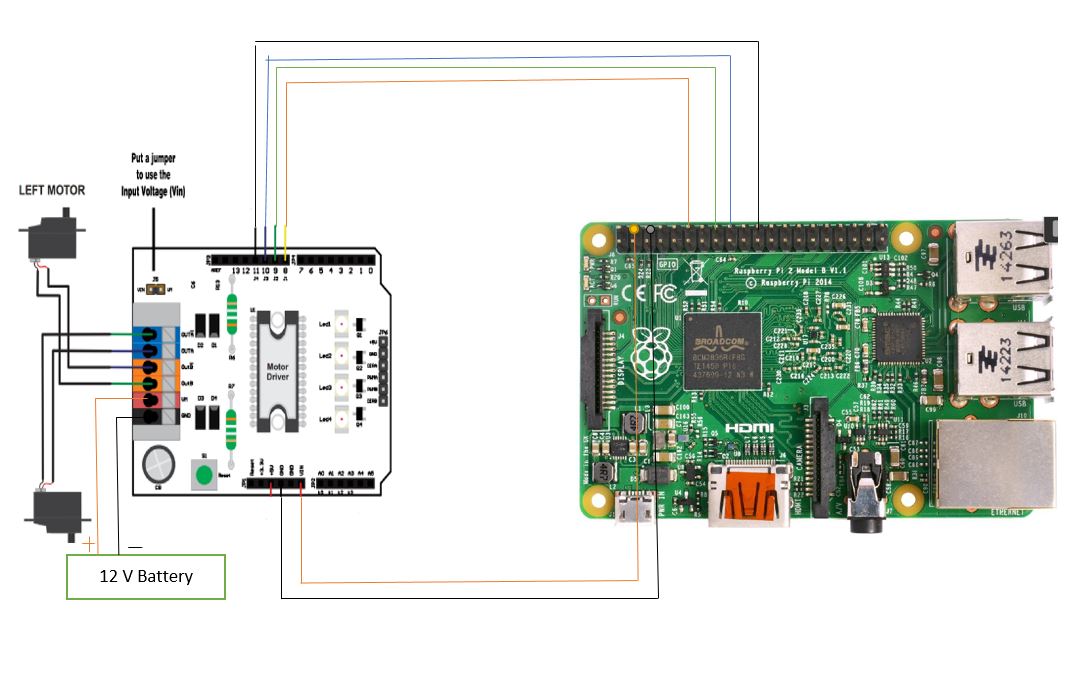
The attached file is the wiring diagram I used. Also a raspberry pi camera is being used while the circuit is connected. What happen? Thanks for the help!
Asked
Active
Viewed 2,686 times
4
goldilocks
- 60,325
- 17
- 117
- 234
kilokhertz
- 51
- 1
- 3
3 Answers
14
The Raspberry Pi requires 5 Volts - if you've fed it 12 Volts you've killed it. Powering the Pi using the GPIO pins bypasses the fuses that might have saved the Pi if you had used the micro USB connector.
If smoke came out - you've provided too much power to the Pi somehow. That board appears to be designed for an Arduino which has 5V outputs, the Pi's GPIO outputs are 3.3V.
CoderMike
- 7,102
- 1
- 11
- 16
4
I agree with the answer by CoderMike that you've probably fried your Pi. Based on the wiring diagram though, I differ in thinking that it might have been avoidable with this hardware if you had connected it different.
You put 5 V into the shield's logic circuits by connecting the shield's Vin to the 5 V pin on the Pi. That's the orange-ish line near the bottom of your figure. You probably then got that same 5 V level running through your GPIO pins, which, as CoderMike said, is going to damage your Pi.
You might be alble to use this same hardware if you connect the Pi's 3.3 V pin to Vin on your shield. Before you try that and maybe burn up more hardware, however, you should read the specification for the shield. Look to see if the shield can operate on 3.3 V, and verify that this connection results in 3.3 V at the GPIO pins.
If you're unsure though, I'd get a motor driver designed for the Pi. That won't be super-expensive and may be less frustrating in the long run - especially if you burn another device trying to make the Arduino shield work on your Pi.
Brick
- 1,375
- 2
- 14
- 20
2
The very first thing you should look at is the datasheet or the reference manual before starting hooking it up.
In this case, the manual has a schematic, so you do know exactly what will happen when you attach the circuit like you did: smoke. The problem, however, is not the logic level of the pins (more on that later), but the Vin voltage. You connected Vin to the +5V rail of the raspberry, and the left this jumper on:
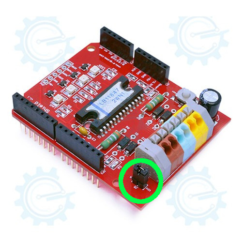
This jumper connects the Vin pin to Vm (your 12V), so... Smoke
The correct connections are GND to the ground pin and +5V to the +5V of the rPI. The Vin pin should be open.
As for the digital I/Os, the schematis says that they enter directly into a transistor; this is strange for me (you will need a resistor if it is not integrated into the transistor itself). For this part, you will have to connect a multimeter (set it to read resistances) between one of the pins and ground (without the board powered). First attach the red cable to the pin and the black to the ground, then connect the black to the pin and the red on the ground. You may face three scenarios:
- If the multimeter reads almost the same value in both cases (it may be something in the range 1k-100k) then the board has integrated resistors
- If the multimeter reads something (maybe under 1k) when the red is connected to the pin, then reads open circuit when the black is connected to the pin, then there aren't integrated resistors
- If the multimeter reads open circuit in both cases, then the pads on the bottom side are not short circuited.
As for case 1, you can directly connect the rPI to the board; I think you will not break anything.
If you are in case 2, you should add a resistor (a couple kOhms is fine) in series with the pin (I mean, one terminal of the resistor in the hole 9, the other connected to the rPI pin for the PWMA).
If you are in case 3, if you look under the board you will see these four pads:

You will have to be sure that they are shorted out (usually a drop of solder will join them). If you don't want to short them, on the side opposite to the colored motor terminals there are six holes; you can use them for the connection to the rPI (there are the +5V, GND and the four control pins). When you decided if solder the pads or use the other pins, repeat the measure.
If you have troubles interpreting the measures, post them as a comment
frarugi87
- 136
- 2