2

I have been developing an expansion board for my RPi Zero, which contains a power supply based on the buck converter TPS62130 (5V/3A) by Texas Instruments, a USB Hub and a CAN Controller/Transceiver MCP25625.

The controller/transceiver is being fed with two voltage leves, 5V from the buck converter to the transceiver and 3.3V from a voltage regulator LM1117-3.3v to the controller. I used a voltage regulator because the 3.3V output from the RPi Zero would not be able to supply the necessary current.

The MCP25625 is basically the MCP2515 controller and the MCP2551 transceiver in the same chip.

Since MCP25625 has the same "register structure" that the MCP2515, I've been trying to use some tutorials for MCP2515.

I am using Raspian with kernel version 4.9

I have modified /boot/config.txt to include:

dtparam=spi=on
dtoverlay=mcp2515-can0,oscillator=8000000,interrupt=12
dtoverlay=spi-bcm2835

But every time I use sudo ip link set can0 up type can bitrate 250000

All I get is Cannot find device "can0" !! Every single time!

When I run dmesg I get:

    mcp251x spi0.0: Cannot initialize MCP2515. Wrong wiring?
    mcp251x spi0.0: Probe failed, err=19

The board is a PCB and everything is soldered just fine, but perhaps I've made some silly mistake in my circuit. Or maybe I'm forgetting some middle step.

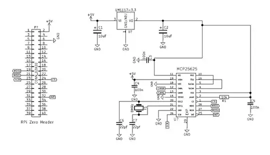
I am attaching part of my schematics in the hopes someone will find my mistake.

Board schematics

Is it really possible to simply change the MCP2515 for the MCP25625?

Have I made some silly mistake in the circuit?
techraf
  • 4,353
  • 10
  • 32
  • 43
eduardoSP
  • 49
  • 2
  • 4

3 Answers3

2

We're using the CAN board from SK-Pang and it wouldn't work on the newer RPi v3 B+ model. dmesg logs gave us the same error message as you.

Turns out they've increased the frequency of the SPI onboard bus which is too fast for the CAN board. Simply decreasing the max SPI frequency solved the issue for us.

Edit /boot/config.txt and alter the overlay configuration to add spimaxfrequency=500000, like this:

dtparam=spi=on
dtoverlay=mcp2515-can0-overlay,oscillator=16000000,interrupt=25,spimaxfrequency=500000
dtoverlay=spi-bcm2835-overlay

Source: I did not discover this, big thanks to chmdebeer in this thread: https://www.raspberrypi.org/forums/viewtopic.php?t=190868

KEK
  • 121
  • 3
1

I had the same issue. I used the following lines in /boot/config.txt

# CAN shield settings from manual
dtparam=spi=on
dtoverlay=mcp2515-can0,oscillator=16000000,interrupt=25
dtoverlay=spi-bcm2835

Notice how mine and your oscillator and interrupt values are different. Once done reboot your RPi.

Then sudo ip link set can0 up type can bitrate 500000 and hopefully that should do the job.

ifconfig should yield a similar result to this:

can0: flags=193<UP,RUNNING,NOARP>  mtu 16
        unspec 00-00-00-00-00-00-00-00-00-00-00-00-00-00-00-00  txqueuelen 10  (UNSPEC)
        RX packets 0  bytes 0 (0.0 B)
        RX errors 0  dropped 0  overruns 0  frame 0
        TX packets 0  bytes 0 (0.0 B)
        TX errors 0  dropped 0 overruns 0  carrier 0  collisions 0

see the same topic.

shmink
  • 137
  • 2
  • 13
0

you dont need the 3v3 regulator, you can run the IC all from your 5v buck, connect VDD,VDDA and VIO all to 5V