This answer intended to answer your specific question, but also to provide an example of an engineering approach to the problem.
How to detect water
There are many ways that water could be detected by a circuit. We could use a float and a microswitch, or a capacitive level sensor, or a float with a magnet and a reed switch, or bounce a laser off the surface of the water into an optical receiver or use an ultrasonic range finder or... you get the idea. However, based on the parts you've already chosen, I'm going to guess that what you intend is to detect the water by passing a small current through it. One way to do this is to have two electrodes with a voltage potential between them. If the two electrodes are in air, no current flows because air is an insulator. If the two electrodes are in water, a small current flows because water conducts. The conductivity of water is somewhere in the range of around 5e-6 S/m (deionized water) to around 5 S/m (seawater), while the conductivity of air is around 5e-9 S/m for relatively humid air. If you're not familiar with it S is for siemens which is just the reciprocal of an ohm.
Some assumptions
Although the Pi has both 5V and 3.3V available, all of its I/O is 3.3V, so let's use that voltage for convenience. Further, let's say that the two electrodes are 1 cm apart. It's not critical that they are exactly this distance apart, but it gives us a reasonable number to use in calculations. Further, let's assume that we want to minimize the cost and complexity of the circuit and its associated software. Further, I'm assuming that it is sufficient to detect the presence or absence of water and that level detection is not a requirement. The rest of this answer proceeds with those assumptions. I'm also going to largely assume that you have read and understood this answer which describes some fundamental concepts about transistor circuit design.
First calculations
First, let's say that we have 3.3V potential across electrodes 1 cm apart and that the medium between the electrodes is air with a conductivity of 5e-9 S/m. The current flowing would be 3.3V * 5e-9 S/m * 0.01 m = 1.65e-10 A or 0.165 nA. That is a very small current, as expected. Now let's repeat the calculation with deionized water with a conductivity of about 5e-6 S/m: 3.3V * 5e-6 S/m * 0.01 m = 165 nA. This is still a small current, but it's a thousand times greater than the current in air, so it may be possible to detect the difference. At the other end of the range, with seawater, we get 3.3V * 5 S/m * 0.01 m = 0.165A = 165mA which is much, much larger. With these calculations, the task is to be able to differentiate between a current of 0.165nA and 165nA. Anything larger than 165nA means that water, or some media that conducts at least as well as water, is between the electrodes.
Another way to look at it is to calculate the resistance. For electrodes separated by 1cm in air, that would be 1 / (0.01 m * 5e-9 S/m) = 20e9 ohms = 20 G ohms. For deionized water this would be 1 / ( 0.01 m * 5e-6 S/m ) = 20e6 ohms = 20 M ohms, and for seawater 1 / ( 0.01 m * 5 S/m ) = 20 ohms.
Transistor circuit design
We want to be able to have a binary output based on whether water is present. That is we want a "yes" or "no" answer. For that reason, we probably want to have the transistor operate like a switch (on/off) rather than as an amplifier. As a practical matter, this usually means operating the transistor not in its linear region, as we would want for an amplifier, but in either fully saturated or fully cut-off. To fully turn on an NPN transistor such as the BC548 you have, typically means applying a voltage of at least 0.7V from B (base) to E (emitter). Let's see if we can do this with a simple voltage divider. What this means is that we'd like to choose a value for R2 so that 3.3 V * R2 / (R1 + R2) = 0.7 when R1 < 20M ohms and close to 0V when R1 > 20M ohms.
If we choose a 10M ohm resistor for R2, it gets us pretty close. Here's a schematic for the resulting circuit:
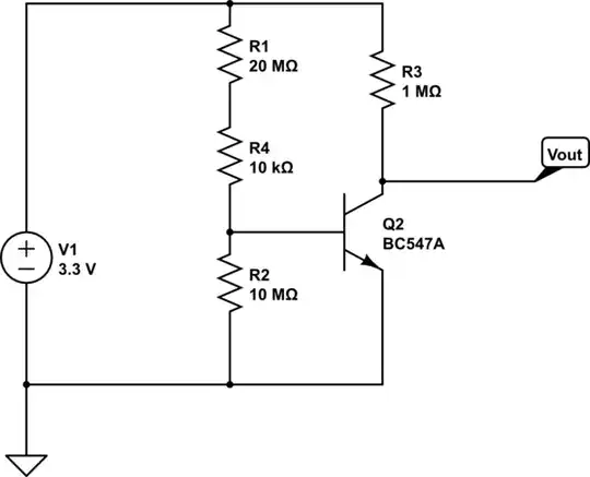
simulate this circuit – Schematic created using CircuitLab
Simulating this circuit with values of R1 ranging from 20 ohms to 20 G ohms, we get the following logarithmic plot of the output voltage:
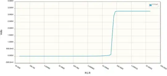
As you can see, there is a fairly sharp transition from 0 to 3.3V right around the 20M ohm value.
Other considerations
By drawing minimal collector current, we can have a nice sharp transition from on to off. That is why R3 has a value of 1M ohm resistor. Finally, consider what would happen if the electrodes were accidentally shorted together. That would effectively make R1 (which represents the resistance of electrodes and the media between them) effectively a 0 ohm connection -- a dead short. If VBE is 0.7V, that means that in order to have a voltage drop of (3.3V - 0.7V = 2.6V), across that short, we need to have infinite current, which is likely to seriously annoy whatever is trying to supply power (your Pi!) and maybe "let the magic smoke out." We don't want that! So for a little bit of safety, we add the 10K resistor R4 which limits the current. Since the values of R1 and R2 are so large, this doesn't affect the voltage much, so the circuit functions about the same way as without it under normal conditions.
Code
Here's a simple flask template. Name this index.html and put it into a directory named templates.
templates/index.html
<html>
<head>
<script>
setTimeout(function() {
    location.reload();
}, 3000);
</script>
</head>
<body>
<h1>Water sensor</h1>
<p>Water was {{ water }} </p>
</body>
</html>
Note that this has a tiny Javascript function that automatically reloads the page every three seconds. It's not a great design, but it will get you started. Next, create the Python code to drive this page. Call it water.py:
water.py
from flask import Flask, render_template
import RPi.GPIO as GPIO

waterpin = 12

app = Flask(__name__)

def water() :
    return ["detected", "not detected"][GPIO.input(waterpin)]

@app.route('/')
def index():
    return render_template('index.html', water=water())

if __name__ == '__main__':
    GPIO.setmode(GPIO.BOARD)
    GPIO.setup(waterpin, GPIO.IN)
    app.run(debug=True, host='0.0.0.0')
Now construct the circuit, keeping in mind that instead of R1, what you'll really have is a pair of wires that will serve as your electrodes. The exact type of transistor is not very critical, but the values of the resistors should be pretty close to what's shown. In my case, I didn't have a 10M resistor, so I used a 3.3M resistor instead, and I didn't have a BCM538, but I happened to have a 2N2222A handy (both are common and inexpensive NPN transistors), so I used that. Connect the ground to ground on the Pi (pin 6), connect the 3.3V line (pin 1 on the Pi) and then connect the line labeled Vout (the collector of the transistor) to a GPIO port (I used pin 12 to be consistent with your earlier attempt).
Results
After installing Flask and the GPIO modules on the Pi. We can run the code from the command line by using the command python3 water.py. By default, this will start a server on port 5000. Navigate to it using either a browser on the Pi itself or on another computer which shares a network connection with it.
I just tried it on a RPi 3 that I have nearby and it worked perfectly.


