9

I am trying to toggle a small relay on and off. I have connected a GPIO pin and GND directly to the relay. I can hear the relay clicking, when I set the GPIO pin to HIGH.

However, the relay only rarely lets a signal through. It works some times, but rarely. If I set the pin to HIGH, and measure the voltage, it is only around 1.6V - so I guess sometimes there is not enough power to drive the relay.

I have previously measured the voltage on the pins, and it read 3.3V. Any ideas on what could be the problem?
goldilocks
  • 60,325
  • 17
  • 117
  • 234
Andreas
  • 193
  • 1
  • 3

3 Answers3

20

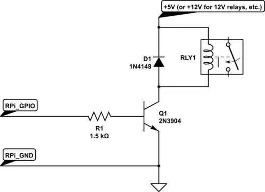
If you want to drive a single low-voltage relay, using a 7-channel driver chip will be an overkill. You'll be perfectly fine with a single NPN transistor and a flyback diode:

schematic

simulate this circuit – Schematic created using CircuitLab

Note: R1 can be replaced by a LED and a 200 - 500 Ohm resistor in series if you want a visual clue about the state of your relay. This is what is often done on pre-made relay boards.

Dmitry Grigoryev
  • 28,277
  • 6
  • 54
  • 147
14

You should not directly drive a relay from the Raspberry Pi. An individual GPIO can only safely provide about 16mA at 3V3 which is unlikely to be enough to energise the coils of a standard electromagnetic relay. Even if you could the back EMF caused by the collapsing magnetic field in the relay coils when it was switched off could destroy a GPIO and the Pi.

You should use the GPIO to switch an external circuit to switch the relay.

Typically a transistor (to amplify the current) and a diode (to protect against back EMF) would be used.

Personally I'd probably use a ULN2003A chip as they were sort of designed for this purpose.

There are lots of relays built into driver boards available for the hobby market.

joan
  • 71,852
  • 5
  • 76
  • 108
0

I have successfully used I2C expander MCP23017 with cheap relay-boards. I have not actully written any how-to's yet but there is plenty around, just look at google and search for "RPI MCP23017".