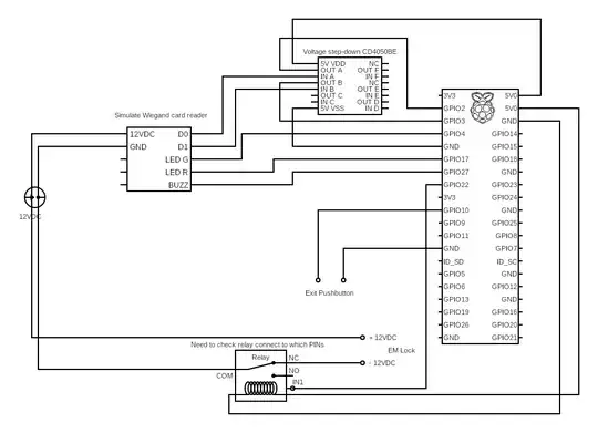
Ok so following on from my previous post here. I have decided to start with the Wiegand wiring interface. I've drawn a diagram below to illustrate how I plan to wire everything up. Would appreciate if any guru can take a look and comment on any mistakes or improvements please. The CD4050BE chip is used to step down the voltage from 5V (coming out of D1/D0) to 3.3V (to the Pi GPIO pins).
One area which I am a little unsure of are my GND connections. Any guidance (or validation) in that specific area would be great as well.
Apologies for the over simplistic line diagram.
EDIT: For the relay, I am using a relay board similar to this. This isn't drawn to detail in the diagram.
