1

Over the past year, I've amassed a box of broken relay modules that have a "voltage drop" problem: When the relay is energized, the voltage measured from the NO terminal and common reads 12V DC, but when I connect it to a solenoid valve, the voltage measured drops to < 1.

It seems to happen most often to the relay controlling the air valve, which is toggled on and off repeatedly, but it's happened to several other valves as well.

Why do some of the relays break / have "voltage drop" ? How can I prevent this from happening?

Notes:

  • The keg cleaner works properly at the moment, after I replaced the broken relay.
  • The solenoid valves require ~1.7A, which the relay modules and transformer can handle.
  • There are at most 5 relays turned on at once, but this only for maintenance procedures. For the cleaning procedure, there are only 2-4 relays on at once, usually only 2.
  • The GPIO pins are also powering 2-3 LEDs. Though I assume this isn't relevant.
  • The relay modules are powered via the raspi.

Devices:

There isn't a spec sheet I could find, so here is the relevant specs from the amazon listing:

  • Optocoupler isolation, good anti-interference.
  • High Level or Low Level Trigger. The status indicator is on when it is engaged, and it is off when it is released.
  • VCC is the system power supply, JD_VCC is the relay power supply. Just plug in the jumper cap.
  • Power supply voltage: 5VDC
  • Current: more than 100mA
  • Load: 250V 10A AC or 30V 10A DC

Wiring instructions: VCC: positive pole of system power supply GND: Negative pole of system power supply IN1--IN2: relay control port (Do not reverse the connection to avoid burning out)

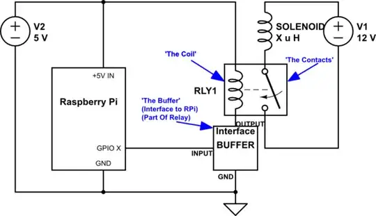
I'm terrible at drawing schematics, so I took a picture of the circuit instead. Please forgive the mess.

Relay Circuit

Any thoughts or suggestions would be greatly appreciated. I'll happily donate a bounty to a correct answer and buy you a cup of coffee (or mail you a bag of our own)!

Lord Elrond
  • 119
  • 6

2 Answers2

1

You could make your question much more clear if you would use the schematic tool instead of relying on verbiage to describe the issue. Consider the following schematic which includes a relay and a solenoid:

Your circuit is wired similarly to the schematic below.

  • The RPi has a 5V power input via the USB connector.

  • You are using a RPi GPIO to control the relay; the 3.3V GPIO signal goes through an Interface/'The Buffer' that is "built in" to the relay.

  • The Interface/'Buffer' presumably acts to provide control of the relay to the GPIO pin on the RPi. IOW, the Interface/'Buffer' is supposed to allow a 3.3V signal produced by the rather fragile MOS transistors inside the RPi to switch current through the relay coil, and thereby control the state of the contacts. When the GPIO switches from LO (~zero volts) to HI (~3V), the relay contacts change state (from closed to open, or from open to closed).

  • When "Normally Open" (NO) contacts become "Closed", current flows from the 12V supply, through the Solenoid (L1), and returns to GND. This in turn causes the valve actuated by the solenoid to open - or close.

schematic

simulate this circuit – Schematic created using CircuitLab

Now - your question says:

When the relay is energized, the NO terminal reads 12V DC, but when I connect it to a solenoid valve, the voltage drops to < 0.

This is NOT as it should be! There are two (2) possibilities:

  1. It's NOT a "Normally Open" (NO) contact at all, but a NC contact.

  2. You have mis-wired something.

Please review & (if necessary) edit your question. Add a schematic to provide details that are not currently included in your question.

Seamus
  • 23,558
  • 5
  • 42
  • 83
0

This is an Electrical Engineering question; the fact that you are running on a Pi does NOT make it a Pi question. In fact you would get the same on any computer (or a microcontroller - which would be cheaper and more reliable).

At an educated guess you have burnt out the relay contacts by repeatedly switching high current inductive loads without a snubber. You have failed to answer the questions about the voltage across the contacts which would confirm.

These cheap relays are not designed for this kind of use; it would be more appropriate to use a MOSFET.

Your question is lacking detail e.g. about how the relay modules are connected.
These poorly designed modules can NOT be controlled by a 3.3V signal (depending on how they are connected). If incorrectly connected they risk damaging the Pi, by putting 5V on GPIO and can result in slow/partial activation which would exacerbate the problem (again simply diagnosed by appropriate measurement.)

Milliways
  • 62,573
  • 32
  • 113
  • 225