1

Recently, I've discovered that I can use the sysfs to control the pwm of my raspberry pi 5. (I don't know about any libraries that are supported buy the pi-5 and can control pwm hardware.) Upon trying to test out the pwm by making an LED 50% brightness I ran into an issue where the pin wasn't outputting any value at all. I'm using pin 18 but I later swapped it to pin 12 (as pwm0 is sometimes pin 12) while troubleshooting - still no change. I also swapped around the period and duty_cycle values a few times from 10,000,000 and 5,000,000 respectively to 5000; 2500, but no change occurred. Here are the commands I used to communicate with the pwm:

cd /sys/class/pwm/pwmchip0
echo 0 > export
cd pwm0
echo ____ > period
echo ____ > duty_cycle
echo 1 > enable

Some things to note: I realized I hadn't setup my pwm command line properly, so I went to /boot/firmware/config.txt and added a line of setup code. Here is the full config.txt file contents. (with the pwm command added)

# Uncomment some or all of these to enable the optional hardware interfaces
dtparam=i2c_arm=on
dtparam=i2s=on
dtparam=spi=on
dtoverlay=pwm-2chan

Enable audio (loads snd_bcm2835)

dtparam=audio=on

Additional overlays and parameters are documented

/boot/firmware/overlays/README

Automatically load overlays for detected cameras

camera_auto_detect=1

Automatically load overlays for detected DSI displays

display_auto_detect=1

Automatically load initramfs files, if found

auto_initramfs=1

Enable DRM VC4 V3D driver

dtoverlay=vc4-kms-v3d max_framebuffers=2

Don't have the firmware create an initial video= setting in cmdline.txt.

Use the kernel's default instead.

disable_fw_kms_setup=1

Run in 64-bit mode

arm_64bit=1

Disable compensation for displays with overscan

disable_overscan=1

Run as fast as firmware / board allows

arm_boost=1

[cm4]

Enable host mode on the 2711 built-in XHCI USB controller.

This line should be removed if the legacy DWC2 controller is required

(e.g. for USB device mode) or if USB support is not required.

otg_mode=1

[cm5] dtoverlay=dwc2,dr_mode=host

[all]

When I went to /sys/kernel/debug/pwm it displayed:

pwm-0 (sysfs): requested enabled period: ___ ns duty: ___ ns polarity: normal

This probably means that the pwm is being outputted somewhere. Does anyone know what might be causing the pin 18/12 to output no value?
Matthew Moller
  • 75
  • 1
  • 12

1 Answers1

1

This seems to work for me:

Load the overlay & "poke around"

$ sudo nano /boot/firmware/config.txt 
# add line: 'dtoverlay=pwm'
# using defaults for 'pin' & 'func' parameters: 18,2
# save & close, then re-boot
# after reboot:
#
$ ls /sys/class/pwm
pwmchip0  pwmchip2  pwmchip6

on RPi 5 the PWM controller is pwmchip2

$ cd /sys/class/pwm/pwmchip2 $ ls -l lrwxrwxrwx 1 root gpio 0 Aug 15 00:25 device -> ../../../1f00098000.pwm --w--w---- 1 root gpio 16384 Aug 15 00:25 export -r--r--r-- 1 root gpio 16384 Aug 15 00:25 npwm drwxrwxr-x 2 root gpio 0 Aug 15 00:25 power lrwxrwxrwx 1 root gpio 0 Aug 15 00:25 subsystem -> ../../../../../../../class/pwm -rw-rw-r-- 1 root gpio 16384 Aug 15 00:25 uevent --w--w---- 1 root gpio 16384 Aug 15 00:25 unexport

Run the following commands in designated folder:

$ cd /sys/class/pwm/pwmchip2

$ echo 2 > export

$ ls -l lrwxrwxrwx 1 root gpio 0 Aug 15 00:25 device -> ../../../1f00098000.pwm --w--w---- 1 root gpio 16384 Aug 15 00:34 export -r--r--r-- 1 root gpio 16384 Aug 15 00:25 npwm drwxrwxr-x 2 root gpio 0 Aug 15 00:25 power drwxrwxr-x 3 root gpio 0 Aug 15 00:34 pwm2 # <== NOTE!! lrwxrwxrwx 1 root gpio 0 Aug 15 00:25 subsystem -> ../../../../../../../class/pwm -rw-rw-r-- 1 root gpio 16384 Aug 15 00:25 uevent --w--w---- 1 root gpio 16384 Aug 15 00:25 unexport

let's have a look in 'pwm2':

$ ls -l pwm2 total 0 -r--r--r-- 1 root gpio 16384 Aug 15 00:34 capture -rw-rw-r-- 1 root gpio 16384 Aug 15 00:36 duty_cycle -rw-rw-r-- 1 root gpio 16384 Aug 15 00:36 enable -rw-rw-r-- 1 root gpio 16384 Aug 15 00:35 period -rw-rw-r-- 1 root gpio 16384 Aug 15 00:34 polarity drwxrwxr-x 2 root gpio 0 Aug 15 00:34 power -rw-rw-r-- 1 root gpio 16384 Aug 15 00:34 uevent

So most files in /sys/class/pwm/pwmchip2/pwm2 look relevant to PWM!

Write some values to files in pwm2:

$ cd /sys/class/pwm/pwmchip2/pwm2

$ echo 2000000 > period

$ echo 1000000 > duty_cycle

$ echo 1 > enable

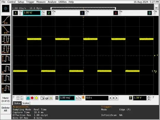
Hopefully, you can now see a square wave w/ 50% duty cycle on GPIO 18 (header pin 12) - as shown below. Change duty_cycle & period to suit your needs.

Following is what I see on my o'scope w/ echo 2000000 > period, and echo 1000000 > duty_cycle:

oscilloscope screenshot


NOTES:

  1. I'm presently unsure what the difference(s) are in the dtoverlays pwm and pwm-2chan. I'll try to scope that out when I've got more time - or maybe you already know? In any case, hopefully this gets you on your way.

  2. The PWM controller for the RPi 5 is not pwmchip0 - it's pwmchip2

  3. The kernel documentation for the PWM device

  4. See this other answer for a how-to on using both hardware PWM channels.

Seamus
  • 23,558
  • 5
  • 42
  • 83