I have a question related to What is the power on state of the GPIOs?
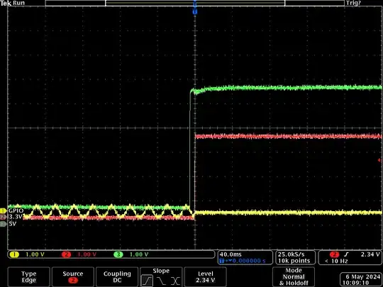
I am aware that GPIO lines on the Raspberry Pi have a defined Pull-Up/-Down state at power up. However, there seems to be an undocumented timing aspect. All of the following oscilloscope traces have been recorded on an RPi4/5 without an SD card.
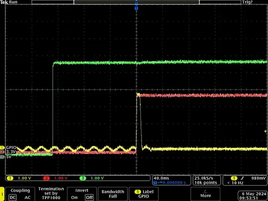
The following image shows an oscilloscope trace of an RPi4 starting up. 3.3V and 5V lines are connected to the respective power rails, GPIO is connected to GPIO20:
I expected GPIO20 to have a pull-down active at power up, but that's not quite happening. One can see that the GPIO pin is first floating, catching a nice 50 Hz noise. Then 5V comes up and a bit later 3.3V as well. And then there's a short spike on the GPIO line. At this point, the GPIO line still does not have a pull-down enabled, the noise is still visible after the spike. Then the pull-down finally becomes active.
The same behavior applies for GPIO pins with a pull-up. This is the same trace for GPIO7:
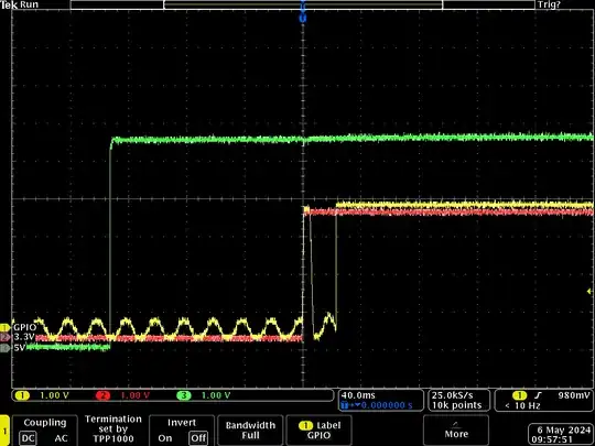
Again there is a spike on the GPIO line before the pull up becomes active.
The impedance of this spike seems to be quite high, here is GPIO20 again, with a 100k pull-down inserted:
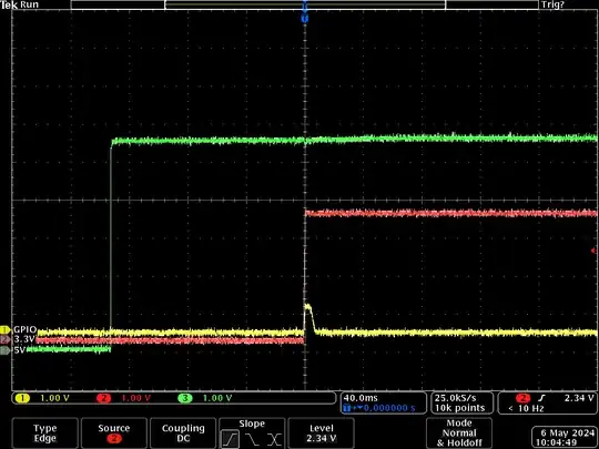 The noise is gone and the spike is signifanctly flattened.
Edit: As suggested by Seamus, I tried a different way of enabling power. Instead of connecting the USB connector, I left that plugged in and connected the power supply to the outlet instead. Result looks identical:
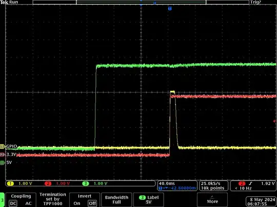
This behavior seems to be specific to the Broadcom GPIO controller. I tried the same experiment with an RPi5 and the behavior is less surprising:
Question:
Is this timing behavior documented anywhere? I could not find a reference to it in the BCM2711 documentation: https://datasheets.raspberrypi.com/bcm2711/bcm2711-peripherals.pdf
Edit: As was helpfully pointed out to me, the RPi4 has a BCM2711. Edited the question.
