0

Very new to GPIO and wiring circuits so I'm hoping someone can clarify whether what I'm doing is going to be safe for the Pi.

In my original question I was looking for the way to get my 12V supply down to a nice voltage for GPIO. After learning about voltage dividers I got a working breadboard layout connected to 4 button/LED combinations using resistors and each mini-circuit got down to 2.34V - safe for GPIO input.

I'm just using GPIO button to check for a closed button - not powering anything thru GPIO

In theory only one button will only ever get pressed at once - but my question/worry is what happens if more than one button gets pressed at same time,- each one supplying 2.34V to separate GPIO inputs? Will the Pi be safe?

My circuit on falstad looks like this - with one switch closed (showing 2.3V)

The 4 center outputs will go to separate GPIO pins on the Raspberry Pi

EDIT: UPDATED CIRCUIT TO SHOW PI CONNECTIONS
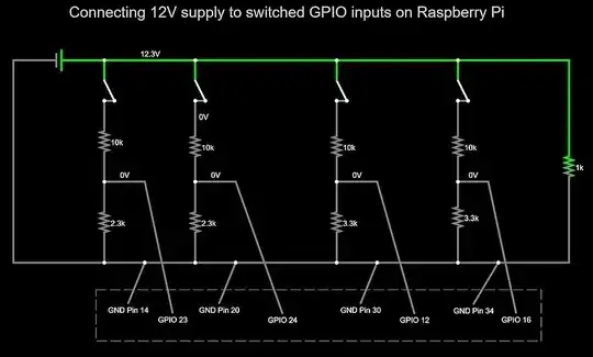
Updated Pi Circuit Connections

dbmitch
  • 401
  • 7
  • 22

3 Answers3

2

Your circuit is good but I am not comfortable with 2.3V as an input, I would change the 10K resistors to about 6.8K bringing the input voltage to just over 3V. That will give you a solid logic 1. I do this with 24VDC and use a similar arrangement but I also add about a 27K to 50K resistor in series from the voltage divider to the port pin. This gives me the voltage I need and does not drive the processor with damaging current if its supply fails and the 24V remains on. This also gives me protection if the bottom resistor opens for some reason, the higher voltage will forward bias the protection diode but not with enough current to damage anything.

Gil
  • 1,288
  • 6
  • 5
1

There is no possible mechanism in which the pressing of 1 or 4 buttons could conceivably change the voltage on the dividers unless you have multiple buttons connected to the GPIO.

Milliways
  • 62,573
  • 32
  • 113
  • 225
1

Your circuit is OK. Each voltage divider is independent from the others, so there's no possible interference between them if you press several buttons. Note that you don't need to connect 4 GND pins, one would be enough, and more wires means more room for mistakes. I would have also set your voltage dividers to a value close to 3.3V, unless you expect your power supply to deliver > 17V under some circumstances.

As a side note, I see you have drawn the circuit diagram in a simulator. Go ahead and run the simulation, then toggle the switches to check the combinations you have in mind. The simulator can plot the voltages on each GPIO in a scope, and you'll clearly see the voltage levels are OK at all times.

Dmitry Grigoryev
  • 28,277
  • 6
  • 54
  • 147