Answer
Discussion
Let us first check out the ADS1256' "Read 2's compliment results and
convert to signed decimal" function.
Update 2020mar02hkt1905
If you have tested you 2's complement to signed decimal converter OK, you can then define the converter as a function, as shown in my ADXL345 demo program, to be used later. This converter function should not be defined in you ASD1256 class, and of course should not be merged with the convert analog to digital function, making debugging difficult.
Now let me suggest how to start testing your ADS1256 class. I found that you just defined the class, but have not shown how to instantiate an ADS1256 object and do the conversion, print the results etc. I usually suggest to do the "ping" thing, ie, read the device ID. In my ADXL345 demo program, you can see that my ping function is to read the device id "0xe5", I have other ping functions for other devices.
I found that your ADS1256 class has a similar ping or read device ID function, as listed below.
def ADS1256_ReadChipID(self):
    self.ADS1256_WaitDRDY()
    id = self.ADS1256_Read_data(REG_E['REG_STATUS'])
    id = id[0] >> 4
    # print 'ID',id
    return id
So my suggestion to start debugging is to do the following:
Write a very simple program to read device ID.
It is only when you have successfully
(1) read the device ID, then you can do
(2) the AD conversion, and
(3) convert to signed decimal and (4) print results.
My ADXL345 demo program is a plug and play self contained program without need of other libraries. If you have ADXL345, then you just run my demo program to get the results.
Then you can translate my program for your ADS1256. There is of course the read negative value, and scaling offset problem not yet solved.
Now I would suggest to solve the problem is two steps,
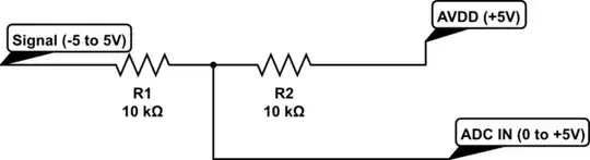
(a) read a standard positive value, say +2.00V, to make sure your scaling and gain is correctly set.,
(b) then set scaling and gain for negative -2.00V.
If your step (a) is debugged, then you are almost there. You can do trials and errors to do setting for negative values.
If you can show me the program listing and sample results like my ADXL345 demo program, I am happy to follow up and make more suggestions or other thing, like how to reduce noises etc.
References
(1) ADS1256 24-bit Analog to Digital Converter Datasheet - TI
Appendices
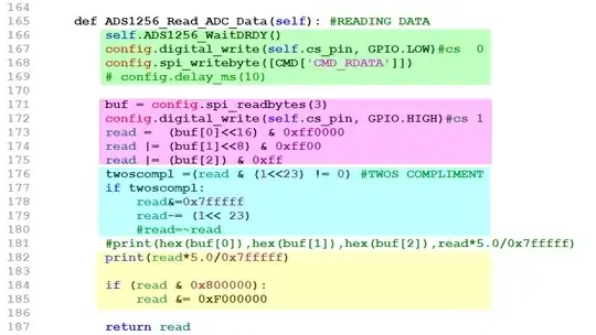
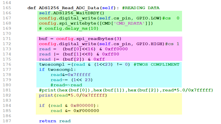
Appendix A - ADS1256 Read three byte long 2's compliment results and convert to signed decimal
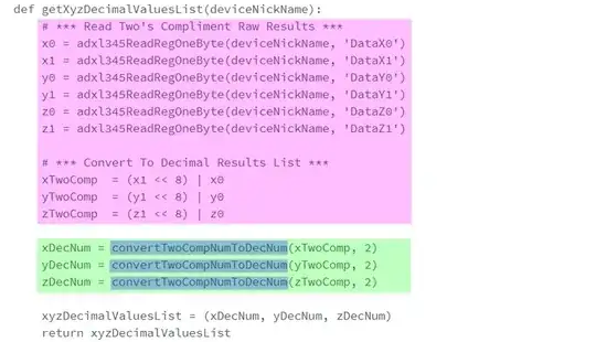
Appendix B - ADXL345 Read three two-byte-long 2's compliment results and convert them to signed decimal
Troubleshooting Tips - Insert break points, fake values, and debugging
print statements statements in the pink and green sections.
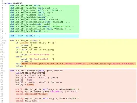
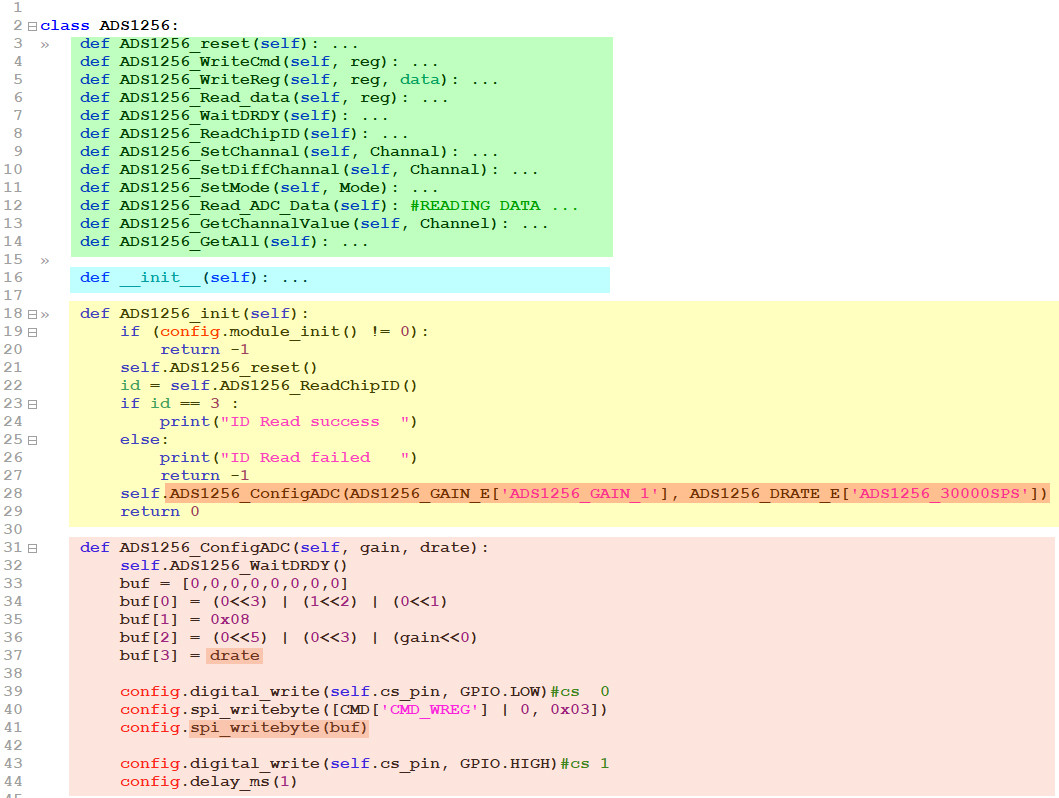
Appendix C - ADS1256 Class
Comment: The class summarized below seems not flexible enough toe test the
ADS1256 ADC device. It would be nice to include a sample instantiation
and methods used to change the parameters such as gain, data rate (or
one shot) with sample outputs, to clarify how a couple of tests have
been made.
