I want to read analog inputs from piezo sensors like these on Raspberry using python, which ADC do you advise me with 8 or more channels and how to wire and program it to get digital values?
Asked
Active
Viewed 2,909 times
1 Answers
1
Question
/ to continue, ...
Answer
Update 2019sep26hkt1626
I googled and found other circuits using a 5V PSU and connects 1M and piezo in series across the PSU. I found without the Zener, the piezo output spikes +-30V. This concludes that piezo output can burst many times up to 30V beyond 5V power. If the same PSU is used to power Rpi, than there is a risk of frying the Rpi.

Now I am using a 5V Zener diode to clamp the 30V+ piezo signal to under 5V. The very high spike gets clamped down, and the following smaller wavelets look OK.
So next step is to try to use MCP3008 to sample the signal. The wave packet is less than 500mS long, amplitude smaller than 5V. So MCP3008 should be able to handle it.
Note - I have first connected the Zener diode to the Piezo, and then the Zener diode to the MCP3008 ADC. In other words, MCP3008 is directly connected to Zener (at points X, Y of picture below), NOT to piezo (points A, B). This way, even if the Zener is disconnected by a careless newbie mistake, any high pulse generated from piezo will not travel to the MCP3008, frying it and its master Rpi.

I tested the piezo disk torn down from another piezo buzzer and found the finger tapping output signal of a different shape from the first one. Anyway, I think the output amplitude under 5V and period of about 500mS good for MCP3008 to do conversion.

I once played with electromagnetic buzzer and used a little audio amplifier to amplifier the buzzer audio output. Now the piezo also outputs audio range signals, so I am thinking of doing the same thing.

/ to continue, ...
References
Resonant frequency: 4.6 +/- 0.5 KHz
Resonant impedance (ohms): 300 max
Plate material: Brass
Great for: Acoustic Instrument Pickups, Stomp Boxes, Contact Mics, etc...
(2) MCP3008 SPI 8 Channel 10 Bit ADC Datasheet - MicroChip
/ to continue, ...
Appendices
(A) Piezo with 1M, no Zener, One slight finger tap gives 30V peak
I was curious to know how high would be the piezo output voltage, without clamping it with a Zener diode. I surprisingly found it as high as 30V! This would fry both the MCP3008 and and it master Rpi!

Conclusion: Zener diode is absolutely necessary!
(B) Piezo Buzzer Tearing Down

/ to continue, ...
(C) The Schematic
Now I am trying to use the RpiSO's built in CircuitLab schematic editor to draw my piezo toy. This editor is newbie friendly. I dragged and pasted the symbols, draw connecting wires, and finally saved and inserted. My masterpiece was automatically inserted here, with the HTML lines inserted along, no need to go outside to ask Imgur for help. Another good thing is that the RpiSO CircuitLab account tlfong01 is automatically created for me. So next time I came back and found my pictures ready for more "final" strokes! One thing not perfect though, is that I cannot "paint" the objects. I need to go outside and asked my PS for help.
...
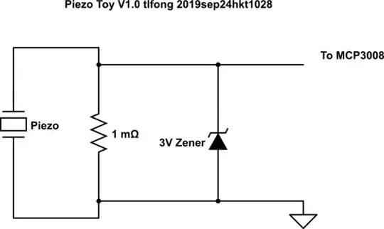
simulate this circuit – Schematic created using CircuitLab
tlfong01
- 4,847
- 3
- 12
- 24