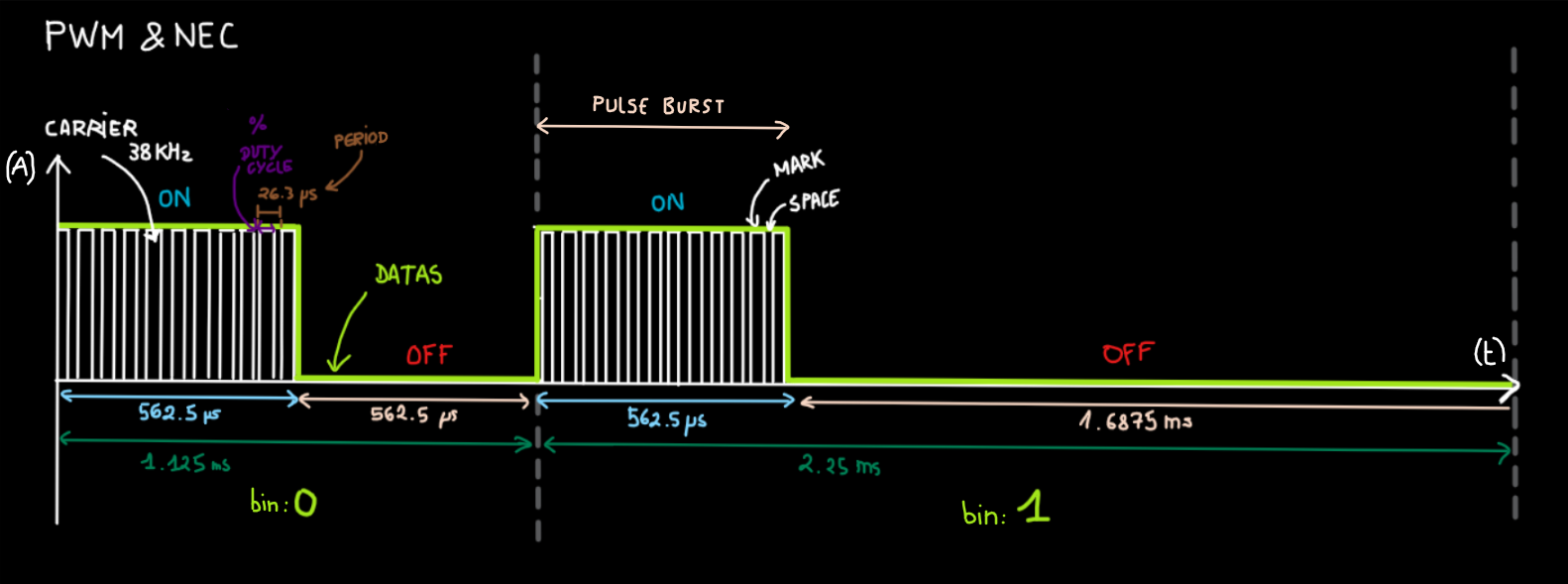
I try to understand how to generate IR carrier frequency with the raspberry and how PWM and NEC work visually. I learn PWM but I cannot find any explication of duty cycle. Ok it's a percentage of HIGH state on 1 cycle or 1 period or 1Hz ... But what is the require duty-cycle for IR LED and what is related to ? I have create this picture :
I have also read this dicussion : Notes-on:-Pulse-Width-Modulation-(PWM) , control-hardware-pwm-frequency and driving-pwm-output-frequency
I have written a script capable to find GPIO PWMC and PWMR configuration values, then the output of my script is:
Enter the frequency in Hz : 38000
Enter the tolerance in % : .1
Tolerance: 0.1% (38 Hz)
PWMC:5, PWMR:101, PWM_RESOLUTION:0.3 us/unit, PWM_PERIOD:26.3 us, PWM_FREQ:38019.8 Hz       DIFF:+19.8 Hz
PWMC:101, PWMR:5, PWM_RESOLUTION:5.3 us/unit, PWM_PERIOD:26.3 us, PWM_FREQ:38019.8 Hz       DIFF:+19.8 Hz
PWMC:505, PWMR:1, PWM_RESOLUTION:26.3 us/unit, PWM_PERIOD:26.3 us, PWM_FREQ:38019.8 Hz      DIFF:+19.8 Hz
PWMC must be only an predefined even number ? (
In this case my script is wrong)
The nearest divider for a 38KHz carrier seems to be BCM2835_PWM_CLOCK_DIVIDER_512 = 512, /*!< 512 = 37.5kHz */