From the MPU-6000/MPU-6050 Register Map and Descriptions:
Section 4.28, Register 107 – Power Management 1 PWR_MGMT_1, pages 40 to 41:
Note:
When using SPI interface, user should use DEVICE_RESET (register 107) as well as SIGNAL_PATH_RESET (register 104) to ensure the reset is performed properly. The sequence used should be:
- Set DEVICE_RESET = 1 (register PWR_MGMT_1)
- Wait 100ms
- Set GYRO_RESET = ACCEL_RESET = TEMP_RESET = 1 (register SIGNAL_PATH_RESET)
- Wait 100ms
Section 4.26, Register 104 – Signal Path Reset SIGNAL_PATH_RESET, page 37:
Note: This register does not clear the sensor registers. The reset initializes the serial interface as well.
Section 3, Register Map, page 8:
The reset value is 0x00 for all registers other than the registers below.
- Register 107: 0x40.
- Register 117: 0x68.
This means that the PWR_MGMT_1 register defaults to sleep mode after a reset so it needs to be rewritten to disable sleep mode after commanding a reset.
void initializeSensor()
{
  //
  // Perfrom full reset as per MPU-6000/MPU-6050 Register Map and Descriptions, Section 4.28, pages 40 to 41.
  //
// performing full device reset, disables temperature sensor, disables SLEEP mode
  Wire.beginTransmission(0x68);  // Device address.
  Wire.write(0x6B);              // PWR_MGMT_1 register.
  Wire.write(0b10001000);        // DEVICE_RESET, TEMP_DIS.
  Wire.endTransmission();
  delay(100);                    // Wait for reset to complete.
Wire.beginTransmission(0x68);  // Device address.
  Wire.write(0x68);              // SIGNAL_PATH_RESET register.
  Wire.write(0b00000111);        // GYRO_RESET, ACCEL_RESET, TEMP_RESET.
  Wire.endTransmission();
  delay(100);                    // Wait for reset to complete.
// Disable SLEEP mode because the reset re-enables it. Section 3, PWR_MGMT_1 register, page 8.
  Wire.beginTransmission(IMUAddress);   // Device address.
  Wire.write(0x6B);                     // PWR_MGMT_1 register.
  Wire.write(0b00001000);               // SLEEP = 0, TEMP_DIS = 1.
  Wire.endTransmission();
}
In the following code I've:
Modified readGyro() to implement 3 states (Request, Wait, and Read) and return true when 6 bytes have been read from the MPU-6050.
Added Blink Without Delay to loop() to see whether the MCU freezes which requires changing the ADO pin from pin 13 (the built-in led) to another pin, i.e. pin 12.
Added several Serial.print() statements for debugging to see where things go wrong.
Tweaked the code in response to comments.
#include <Wire.h>
const byte IMUAddress = 0x68; // Added for readability and maintainability.
const byte addressPin = 12; // Changed from 13 to 12 because 13 is built-in LED.
int gyroX, gyroY, gyroZ;
void setup()
{
Wire.begin();
Serial.begin(115200);
Serial.println(F("\n\nMPU-6050 Test\n"));
// Designating pins as I/O.
pinMode(addressPin, OUTPUT);
pinMode(LED_BUILTIN, OUTPUT); // Added LED for heartbeat signal.
// Setting IMU address to 0x68 (LOW).
digitalWrite(addressPin, IMUAddress & 1); // Added bit mask of bit 0.
initializeSensor();
}
void loop()
{
//
// TASK 1: Blink without delay to indicate that MCU hasn't frozen.
//
const unsigned int INTERVAL = 250;
unsigned long current_timestamp = millis();
static unsigned long previous_timestamp = current_timestamp;
static bool led_state = false;
if (current_timestamp - previous_timestamp >= INTERVAL)
{
led_state = !led_state;
digitalWrite(LED_BUILTIN, led_state);
previous_timestamp += INTERVAL;
}
//
// TASK 2: Read gyro.
//
if (readGyro())
{
Serial.print(gyroX);
Serial.print(F(" "));
Serial.print(gyroY);
Serial.print(F(" "));
Serial.println(gyroZ);
}
}
void initializeSensor()
{
//
// Perform full reset as per MPU-6000/MPU-6050 Register Map and Descriptions, Section 4.28, pages 40 to 41.
//
Serial.print(F("Performing full reset of MPU-6050..."));
Wire.beginTransmission(IMUAddress); // Device address.
Wire.write(0x6B); // PWR_MGMT_1 register.
Wire.write(0b10001000); // DEVICE_RESET, TEMP_DIS.
Wire.endTransmission();
delay(100); // Wait for reset to complete.
Wire.beginTransmission(IMUAddress); // Device address.
Wire.write(0x68); // SIGNAL_PATH_RESET register.
Wire.write(0b00000111); // GYRO_RESET, ACCEL_RESET, TEMP_RESET.
Wire.endTransmission();
delay(100); // Wait for reset to complete.
Serial.println(F(" Done."));
// Disable SLEEP mode because the reset re-enables it. Section 3, PWR_MGMT_1 register, page 8.
Serial.print(F("Disabling sleep mode of MPU-6050..."));
Wire.beginTransmission(IMUAddress); // Device address.
Wire.write(0x6B); // PWR_MGMT_1 register.
Wire.write(0b00001000); // SLEEP = 0, TEMP_DIS = 1.
Wire.endTransmission();
Serial.println(F(" Done."));
//
// Writing to gyro config register.
//
Serial.print(F("Configuring gyro of MPU-6050..."));
Wire.beginTransmission(IMUAddress); // Device address.
Wire.write(0x1B); // GYRO_CONFIG register.
Wire.write(0b00001000); // +/-500 deg/s.
Wire.endTransmission();
Serial.println(F(" Done."));
}
typedef enum State
{
Request,
Wait,
Read
};
bool readGyro()
{
static State state = State::Request;
switch (state)
{
case State::Request:
// Request data from gyro data registers.
Serial.print(F("Requesting data from gyro..."));
Wire.beginTransmission(IMUAddress); // Device address.
Wire.write(0x43); // GYRO_XOUT_H register.
Wire.endTransmission(false); // Restart connection, i.e. keep alive.
Wire.requestFrom(IMUAddress, 6); // GYRO_XOUT_H, GYRO_XOUT_L, GYRO_YOUT_H, GYRO_YOUT_L, GYRO_ZOUT_H, GYRO_ZOUT_L.
Serial.println(F(" Done."));
state = State::Wait;
Serial.print(F("Waiting for data from gyro..."));
break;
case State::Wait:
// Wait for data to arrive into buffer.
if(Wire.available() < 6)
{
//Serial.print(F("."));
Serial.print(F(" "));
Serial.print(Wire.available()); // Added to show bytes received.
}
else
{
Serial.print(F(" "));
Serial.print(Wire.available()); // Added to show bytes received.
Serial.println(F(" Done."));
state = State::Read;
}
break;
case State::Read:
// Read data from gyro registers.
Serial.print(F("Reading gyro data..."));
gyroX = Wire.read() << 8 | Wire.read();
gyroY = Wire.read() << 8 | Wire.read();
gyroZ = Wire.read() << 8 | Wire.read();
Serial.println(F(" Done."));
state = State::Request;
return true; // Indicate data was received.
break;
}
return false; // Indicate no data received yet.
}
Update based upon RowanP's answer
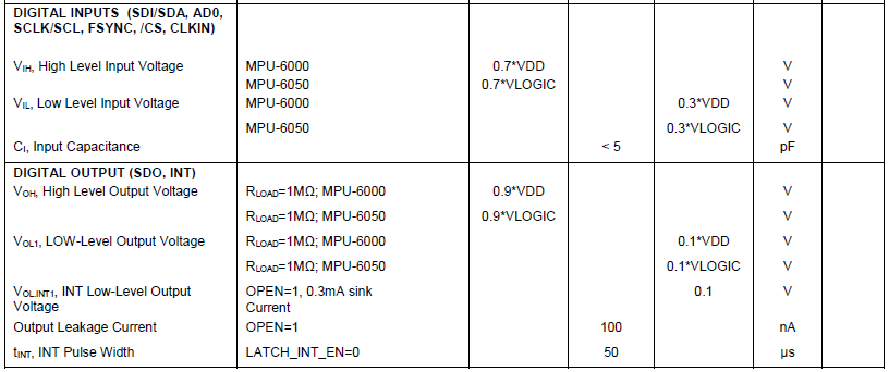
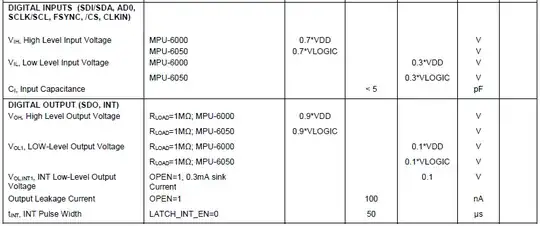
While concentrating on the software issues I missed a crucial piece of information from the other datasheet (MPU-6000/MPU-6050 Product Specification), i.e. the electrical characteristics in Sections 6.3 and 6.4 on pages 14 and 15 showing a Vdd range of 2.375 V to 3.46 V:

6.4 Electrical Specifications, Continued
This will require level shifters on the signals between the 3.3 V MPU-6050 and the 5 V Arduino.