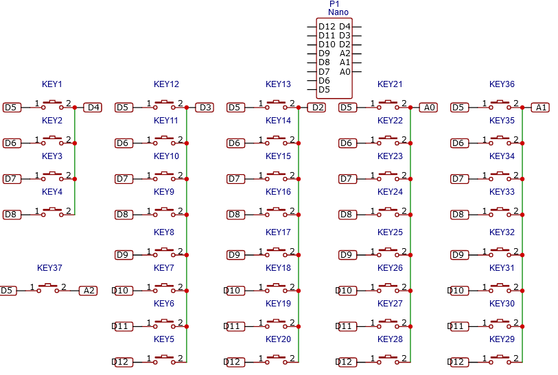
I'm trying to use a cheap keyboard with 37 keys as a MIDI controller by reading the multiplexed keys with an Arduino nano. The keys are grouped in six groups with a max of 8 keys per group. Which results in my setup of 8 digital INPUTS which are pulled HIGH, and 6 OUTPUTS, which are pulled LOW, when reading that group of keys. This works great when I only have 3 groups in my loop. However whenever I add another group it does not work anymore. It doesn't matter which groups are activated.
One group reading looks like this:
digitalWrite(A0, LOW);
for (byte j = 12; j > 4; j--)
{
  uint8_t note = offset + 20 + (12-j);
  uint8_t key_state = digitalRead(j);
if ( (key_state == 0) && (notes_pressed[note] == 1) )
  {
    notes_pressed[note] = 0;
    Serial.write(note + 100);
  } else if ( (key_state == 1) && (notes_pressed[note] == 0) )
  {
    notes_pressed[note] = 1;
    Serial.write(note);
  }
}
digitalWrite(A0, HIGH);
With A0 being the group pin.
I think this has to do with the pins not being able to be pulled low as quickly because of weak output drivers or something similar. Unfortunately I don't have an oscilloscope to check the levels. I have added delays to ensure the levels have settled when the reading occurs but to no avail.
Edit:
Schematic is pretty much just this. The diodes in the keyboard I left out, but they are there as necessary:
#include "HardwareSerial.h"
#define offset 48
void midi_note_off(byte channel, byte key, byte velocity);
void midi_note_on(byte channel, byte key, byte velocity);
void midi_command(byte command, byte channel, byte param1, byte param2);
byte notes_pressed[37];
void setup() {
  Serial.begin(115200);
  pinMode(12, INPUT_PULLUP);
  pinMode(11, INPUT_PULLUP);
  pinMode(10, INPUT_PULLUP);
  pinMode(9, INPUT_PULLUP);
  pinMode(8, INPUT_PULLUP);
  pinMode(7, INPUT_PULLUP);
  pinMode(6, INPUT_PULLUP);
  pinMode(5, INPUT_PULLUP);
  pinMode(4, OUTPUT);
  pinMode(3, OUTPUT);
  pinMode(2, OUTPUT);
  pinMode(A2, OUTPUT);
  pinMode(A1, OUTPUT);
  pinMode(A0, OUTPUT);
digitalWrite(4, HIGH);
  digitalWrite(3, HIGH);
  digitalWrite(2, HIGH);
  digitalWrite(A0, HIGH);
  digitalWrite(A1, HIGH);
  digitalWrite(A2, HIGH);
}
void loop() {
  digitalWrite(4, LOW);
  for (byte j = 8; j > 4; j--)
  {
    uint8_t note = offset + (8-j);
    uint8_t key_state = digitalRead(j);
if ( (key_state == 0) && (notes_pressed[note] == 1) )
{
  notes_pressed[note] = 0;
  Serial.write(note + 100);
} else if ( (key_state == 1) && (notes_pressed[note] == 0) )
{
  notes_pressed[note] = 1;
  Serial.write(note);
}

}
  digitalWrite(4, HIGH);
digitalWrite(3, LOW);
  for (byte j = 12; j > 4; j--)
  {
    uint8_t note = offset + 4 + (12 - j);
    uint8_t key_state = digitalRead(j);
if ( (key_state == 0) && (notes_pressed[note] == 1) )
{
  notes_pressed[note] = 0;
  Serial.write(note + 100);
} else if ( (key_state == 1) && (notes_pressed[note] == 0) )
{
  notes_pressed[note] = 1;
  Serial.write(note);
}

}
  digitalWrite(3, HIGH);
digitalWrite(2, LOW);
  for (byte j = 12; j > 4; j--)
  {
    uint8_t note = offset + 12 + (12-j);
    uint8_t key_state = digitalRead(j);
if ( (key_state == 0) && (notes_pressed[note] == 1) )
{
  notes_pressed[note] = 0;
  Serial.write(note + 100);
} else if ( (key_state == 1) && (notes_pressed[note] == 0) )
{
  notes_pressed[note] = 1;
  Serial.write(note);
}

}
  digitalWrite(2, HIGH);
digitalWrite(A0, LOW);
  for (byte j = 12; j > 4; j--)
  {
    uint8_t note = offset + 20 + (12-j);
    uint8_t key_state = digitalRead(j);
if ( (key_state == 0) && (notes_pressed[note] == 1) )
{
  notes_pressed[note] = 0;
  Serial.write(note + 100);
} else if ( (key_state == 1) && (notes_pressed[note] == 0) )
{
  notes_pressed[note] = 1;
  Serial.write(note);
}

}
  digitalWrite(A0, HIGH);
digitalWrite(A1, LOW);
  for (byte j = 12; j > 4; j--)
  {
    uint8_t note = offset + 28 + (12-j);
    uint8_t key_state = digitalRead(j);
if ( (key_state == 0) && (notes_pressed[note] == 1) )
{
  notes_pressed[note] = 0;
  Serial.write(note + 100);
} else if ( (key_state == 1) && (notes_pressed[note] == 0) )
{
  notes_pressed[note] = 1;
  Serial.write(note);
}

}
  digitalWrite(A1, HIGH);
digitalWrite(A2, LOW);
  for (byte j = 5; j > 4; j--)
  {
    uint8_t note = offset + 36 + (5-j);
    uint8_t key_state = digitalRead(j);
if ( (key_state == 0) && (notes_pressed[note] == 1) )
{
  notes_pressed[note] = 0;
  Serial.write(note + 100);
} else if ( (key_state == 1) && (notes_pressed[note] == 0) )
{
  notes_pressed[note] = 1;
  Serial.write(note);
}

}
  digitalWrite(A2, HIGH);
}
I know the last part looping over a single value is unnessecary but it should still work.