This answer is based on a previous version of the question
Not necessarily. You can use the internal pullups of the arduino if you're willing to accept that reading a "1" means that no piece is there and reading a "0" means a piece is there.
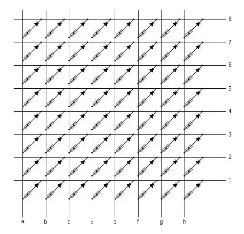
Connect each wire up to a pin on the arduino. If you do it wisely, step 3 becomes fairly easy.
You need to configure the pins connected to the letter wires as inputs with their pullups enabled. Set the number pins to inputs as well, but without the pullup enabled so that they are floating. The number pins will be each set as an output in sequence with the value being low (non-active number pins are set back to inputs). As you do so, you can read the pins on the letter wires and build a picture of the board.
Example
This is how I would do it just taking a naive stab at it. I'm sure there are more effective ways to do this.
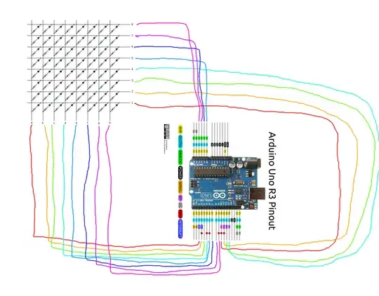
Wiring:
Configure the outputs and inputs in setup:
pinMode(2, INPUT_PULLUP);
pinMode(3, INPUT_PULLUP);
pinMode(4, INPUT_PULLUP);
pinMode(5, INPUT_PULLUP);
pinMode(6, INPUT_PULLUP);
pinMode(7, INPUT_PULLUP);
pinMode(8, INPUT_PULLUP);
pinMode(9, INPUT_PULLUP);
pinMode(10, INPUT);
pinMode(11, INPUT);
pinMode(12, INPUT);
pinMode(13, INPUT);
pinMode(14, INPUT); //A0
pinMode(15, INPUT); //A1
pinMode(16, INPUT); //A2
pinMode(17, INPUT); //A3
pinMode(18, INPUT); //A4
Make a function to scan the rows into an array of bytes:
void scan_rows(uint8_t *rows)
{
    uint8_t i, j;

    for (i = 0; i < 8; i++)
    {
        if (i)
        {
            pinMode(i+9, INPUT);
        }
        pinMode(i+10, OUTPUT);
        digitalWrite(i+10, LOW);
        for (j = 2; j <= 9; j++)
        {
            rows[i] <<= 1;
            if (digitalRead(j))
                rows[i] |= 1;
        }
    }
    pinMode(18, INPUT);
}
Now, just call that function with a pointer to an array with 8 bytes in it whenever you need to scan the board. Each byte in the array represents one of the rows and each bit represents a column.
[moderator note: This answer appears in this thread as a result of a merge]