I'm doing an rfid project that requires a read range of at least 5 inches or about 13cm. I'm using a nano with a usb port, a rfid reader from priority 1 design and a large antenna. The problem I'm running in to is that when I power the project from the usb port I get a pretty decent read range of 11-13cm. But when I power the project from a DC power supply the read range drops considerably.
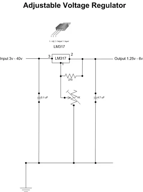
After a lot of testing with various power supplies I believe that all my power adaptors are dirty enough to cause rf interference and reduce the range. Powering the project with a 9v battery and a 5v power regulator gives me really good range: 18cm with the largest antenna. But I need plug in power.
So how can I power this project in a way that gives me ultra clean power?
I tried that same 5v regulator with a 5v adaptor and still had short read range.
Someone suggested adding a smoothing capacitor between V+ and Gnd but I wouldn't know what size. I'm not an EE - I'm just a coder with a soldering iron.
Is there a better power supply I can get?
[EDIT] Also just FYI, when I connect even only the ground wire the the computers USB port I get a much farther read range. So..
- Could it be a case of needing to ground the circut better as the switching power supplies only have 2 prongs and probably no real "ground". (Or am I making stuff up?)
[EDIT 2] What about a rechargable situation where my wall adaptor keeps a litium charged and the litium supplies clean power to the circuit?
Also I now know that I can charge my whole circuit with anything from 5 to 12 volts. In fact it would be better to have more in the 7 to 12 range than strictly 5v.
[UPDATE 3] Since this project is in my wall I was able to ground essentially to "earth" and that cleared up the noise. See this question as well: https://electronics.stackexchange.com/questions/230024/grounding-dc-project-to-clean-rf-noise
