3

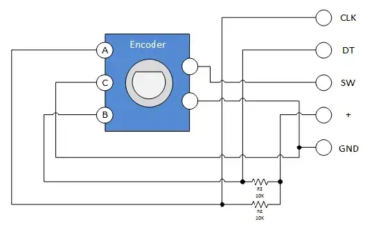
I have a rotary encoder KY-040 connected to a Digispark like this:

enter image description here

CLK go to p0 and and DT go to p2, SW is disconnected for now (it's just a button).

I did everything like the instructions here: http://henrysbench.capnfatz.com/henrys-bench/keyes-ky-040-arduino-rotary-encoder-user-manual/

#include <DigiKeyboard.h>

 int pinA = 0;  // Connected to CLK on KY-040
 int pinB = 2;  // Connected to DT on KY-040
 int encoderPosCount = 0; 
 int pinALast;  
 int aVal;
 boolean bCW;

 void setup() { 
   pinMode (pinA,INPUT);
   pinMode (pinB,INPUT);
   /* Read Pin A
   Whatever state it's in will reflect the last position   
   */
   pinALast = digitalRead(pinA);   
   Serial.begin (9600);
 } 

 void loop() { 
   aVal = digitalRead(pinA);
   if (aVal != pinALast){ // Means the knob is rotating
     // if the knob is rotating, we need to determine direction
     // We do that by reading pin B.
     if (digitalRead(pinB) != aVal) {  // Means pin A Changed first - We're Rotating Clockwise
       encoderPosCount ++;
       bCW = true;
     } else {// Otherwise B changed first and we're moving CCW
       bCW = false;
       encoderPosCount--;
     }
     Serial.println("Rotated: ");
     if (bCW){
       //Serial.println ("clockwise");
       DigiKeyboard.sendKeyStroke(KEY_V); //or DigiKeyboard.write("1");
     }else{
       //Serial.println("counterclockwise");
        DigiKeyboard.println("cc");     
     }
     Serial.print("Encoder Position: ");
     Serial.println(encoderPosCount);

   } 
   pinALast = aVal;
 } 

I only changed the pin numbers in the code and the Serial.println (... to any of the following:

DigiKeyboard.write("1");
DigiKeyboard.println("1");
DigiKeyboard.sendKeyStroke(KEY_V);

All of them didn't do anything when rotating the knob...

Any ideas? Maybe the 10K resistors are too much?
shinzou
  • 155
  • 1
  • 3
  • 9

2 Answers2

4

Shown below is a KY-040 test program that in my tests doesn't lose any counts and is more accurate than some other software; it picks up the counts between detents as well as those at detents. You may be able to adapt it to your DigiKeyboard ATtiny system.

/*  roto_jw4.ino -- JW, 29 September 2015 -- 
 *  A 4-state state-machine implementation of rotary
 *  encoding for KY-040 rotary knobs.  The state-machine picture at
 *  https://e2e.ti.com/support/microcontrollers/hercules/f/312/t/318762
 *  in a Feb 4, 2014 7:40 PM post by Anthony Seely shows counts
 *  increasing on transitions 10 -> 11 -> 01 -> 00 -> 10 and
 *  decreasing on transitions the other way.  Transitions between 00
 *  and 11 or 10 and 01 are invalid.  This code detects valid
 *  transitions by (abOld xor abNew) equaling 1 or 2.  It detects
 *  up-count events by the tri-bit value ABA' (where A' is the new
 *  reading on pin A) being equal to 1, 2, 5, or 6 (a bit mask of
 *  0x66), and down-count events by ABA' being equal to 0, 3, 4, or 7
 *  (a bit mask of 0x99).
 *
 *  On a KY-040 unit I tested, there are 30 detent positions per turn.
 *  With this unit the code generates 60 counts per turn, which can be
 *  seen individually as one turns the rotor slowly.  Odd counts
 *  appear between detents, even counts at detents.
 *
 *  Set quadrature-signal pin numbers, via PinA and PinB constants.
 *  Set IPINMODE to INPUT_PULLUP if there are no external pull-ups
 *  on encoder AB pins, else set IPINMODE to INPUT
 */
enum { PinA=2, PinB=3, IPINMODE=INPUT };

static  byte abOld;     // Initialize state
volatile int count;     // current rotary count
         int old_count;     // old rotary count

void setup() {
  pinMode(PinA, IPINMODE);
  pinMode(PinB, IPINMODE);
  attachInterrupt(0, pinChangeISR, CHANGE); // Set up pin-change interrupts
  attachInterrupt(1, pinChangeISR, CHANGE);
  abOld = count = old_count = 0;
  Serial.begin(115200);
  Serial.println("Starting Rotary Encoder Test");
}

// On interrupt, read input pins, compute new state, and adjust count
void pinChangeISR() {
  enum { upMask = 0x66, downMask = 0x99 };
  byte abNew = (digitalRead(PinA) << 1) | digitalRead(PinB);
  byte criterion = abNew^abOld;
  if (criterion==1 || criterion==2) {
    if (upMask & (1 << (2*abOld + abNew/2)))
      count++;
    else count--;       // upMask = ~downMask
  }
  abOld = abNew;        // Save new state
}

void loop() {
  if (old_count != count) {
    Serial.print(millis());
    Serial.print("  ");
    Serial.println(count);
    old_count = count;
  }
}

Since some ATtiny's only have one external-interrupt pin, it may be necessary to use two pin-change interrupts instead of two external-interrupt pins. (Six of the pins on an ATtiny45, for example, support pin-change interrupts, and only one is an external-interrupt pin.) Change PinA and PinB to appropriate pin numbers, and replace

  attachInterrupt(0, pinChangeISR, CHANGE); // Set up pin-change interrupts
  attachInterrupt(1, pinChangeISR, CHANGE);

with

  enableInterrupt(PinA, pinChangeISR, CHANGE); // Set up pin-change interrupts
  enableInterrupt(PinB, pinChangeISR, CHANGE);

and add the following #include near the beginning:

#include <EnableInterrupt.h>

To install the .h file for use via the Arduino IDE, unpack an EnableInterrupt zip file (for example, enableinterrupt-0.8.2.zip from bintray.com/greygnome) in the directory ~/sketchbook/libraries. I think the package works with ATtiny's as well as more-standard Arduinos.

James Waldby - jwpat7
  • 8,920
  • 3
  • 21
  • 33
2
 int pinA = 0;  // Connected to CLK on KY-040
 ...
   Serial.begin (9600);

Hardware Serial uses pins 0 and 1. I would try other pins. (Oh, it's an ATtiny - well I'm not sure about HardwareSerial on that, but it looks suspicious).

See my page about rotary encoders for more ideas.


I only changed the pin numbers in the code and the Serial.println (... to any of the following:

Maybe post the code you actually used, that would be helpful. Not some code you didn't use.


Maybe the 10K resistors are too much?

No, that looks fine.

Nick Gammon
  • 38,901
  • 13
  • 69
  • 125