17

Increase the number of digital pins

There are many posts that explain how to use more than just the standard pins on the various Arduinos, but none of them properly explain the limitations and problems.

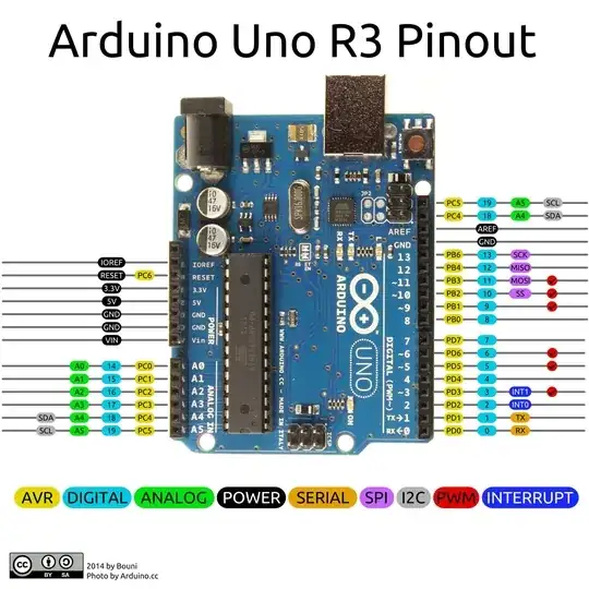
Uno pinout

Arduino Uno:

1. You can use the analog pins

Pin 14 = Analog in 0
Pin 15 = Analog in 1
Pin 16 = Analog in 2
Pin 17 = Analog in 3
Pin 18 = Analog in 4
Pin 19 = Analog in 5

digitalWrite(14,HIGH); or digitalWrite(A0,HIGH);

2. You can't use both SDA , SCL & A4 , A5 as they are basically the same (18,19).

3. You can also use the TX/RX.

"Don't do it, you break the serial communication..."

"Never use pins 0 and 1."

"You can't use the TX/Rx Pins."

You can... but you need to take precautions. Which ones?

It should have software serial over USB, right?

Or do I break the USB serial?

Are there internal Chip problems if I use TX/RX?

As I use those TX/RX pins in the code, I probably should not use Serial.print()?

What happens if I forget to remove Serial.print() after uploading the code that uses pins 0 and 1?

How to hardware reset the Arduino/bootloader if something goes wrong?

As there are various other Arduinos that use different chips, is the above valid for all Atmel chips?

So, what should I know before using those TX/RX, or also maybe the other analog pins?

There are cheap shift registers, PWM drivers, LED drivers, SPI, I2C, and more ICs to expand your I/O


But if there are no too big problems, it means that the Arduino has 20 I/O pins...

You could theoretically control:

17x3 = 51 = 17 RGB LEDs (multiplexing, PWMsourcing & sinking);
14x6 = 84 LEDs (multiplexing, PWM on 6 rows/columns);
10x10 = 100 LEDs (multiplexing, high-low);
20x(20-1) = 380 LEDs (charlieplexing, high-low);
// yes it would flicker

Correct me if I'm wrong. That means you are able to control 380 "Whatever" using diodes and one Arduino.
Greenonline
  • 3,152
  • 7
  • 36
  • 48
cocco
  • 451
  • 5
  • 7
  • 16

3 Answers3

14

The main issue is with pins 0 and 1.

Many pins have multiple functions assigned to them, such as A4 and A5 are also the I2C pins, pins 10/11/12/13 are also the SPI pins, etc. But pins 0 and 1 are the only multi-function pins that actually have something attached to them on the board.

All the other pins, while being multi-function, have their function defined basically by what you attach to them. Since the pins 0 and 1 are already attached on the board to the USB interface chip their usage possibilities are somewhat more limited.

  • As soon as you enable Serial in your sketch (Serial.begin()) those two pins can no longer be reliably used for digital IO.

That means that you can either use the hardware serial port or you can use the pins for digital IO, but not both.

  • Devices connected to pins 0 and 1 can interfere with the serial connection

That includes uploading of sketches. You have serial data coming in from the PC while the same pins are being affected by other things connected to them. The most common one is things like GPS modules which connect to those pins and constantly send serial data. That serial data will conflict with the PC's serial data and neither will arrive right.

  • How do you upload sketches if the serial is being interfered with by your sketch? How do you "reset" the board?

You don't. It's not your sketch that's interfering with the serial, it's what is physically connected to those two IO pins that are interfering. Just disconnect those two pins from whatever is connected and you will be able to upload sketches again. Many shields now are starting to add a small switch on them to disconnect those pins so you can upload sketches without unplugging the shield. You can also use the same trick with other devices you wire up to those pins - add a double-pole-single-throw or double-pole-double-throw (and not use one position) to easily isolate both pins from the rest of your hardware when you need to.

  • Does this affect all Arduino boards?

No, only those that use a USB to Serial bridge chip - that's things like the Uno, Due, Mega, etc. Boards that have a direct USB connection don't use the TX and RX pins for uploading sketches - they use the dedicated USB D+ and D- pins. That's boards like the Leonardo, some of the smaller (mini? micro? I forget which) boards, etc.

Majenko
  • 105,851
  • 5
  • 82
  • 139
4

I can't comment due to insufficient reputation but I want to point out that the OP pinout has at least one pin wrong!

PB6 should be PB5

I spent quite a lot of time trying to figure out why I couldn't see SCK on scope (SPI bus). I was working low level, not with the IDE.

As this is the first picture that comes up when googling I wanted to avoid the same trouble to others...

Petrus
  • 171
  • 1
0

20x(20-1) = 380 leds (charlieplexing, high low); Correct me if i'm wrong. That means you are able to control 380 "Whatever" using diodes and one Arduino.

First, the figure of 380 is correct for 20 pins (202 - 20) however pins 0 and 1 are connected to pull-up resistors on the Atmega16U2, so they are never really at 0V. If you load a blank sketch, you will measure 5 V on pins 0 and 1.

Second, you can't drive 380 "whatevers" you can drive 380 LEDs via Charlieplexing. The property of the LED, that current only flows one way through it, is important to the way it works.

Related question Is there a way to have more than 14 Output pins on arduino?

Nick Gammon
  • 38,901
  • 13
  • 69
  • 125