I have been building a standalone Arduino on a breadboard following the guide, Building an Arduino on a Breadboard. The guide is generally very good, however, I have yet to get the Arduino working, for a number of various reasons, be it misinterpreted, or misread instructions (the reset pull-up resistor connected to GND instead of Vcc, Tx to Tx, instead of Tx to Rx (and vice versa), to name but a few issues that I have had to resolve). However, I am sure that the following issue is not down to my careless interpretation or lack of attention.
Look at the photo taken from the webpage, Building an Arduino on a Breadboard, on the Arduino website, showing the Sparkfun AVR programming adapter connected to the ATmega IC.
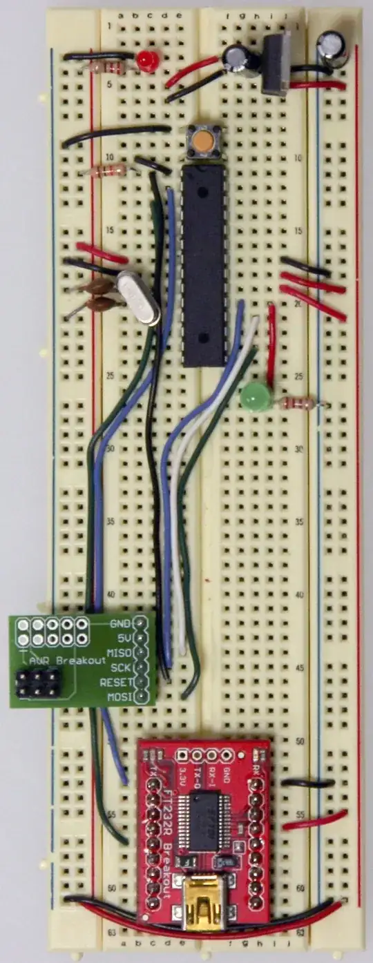
The MOSI on the adapter is shown to be connected, via a dark green wire, to pin 16 on the ATmega chip, whereas the instructions say:
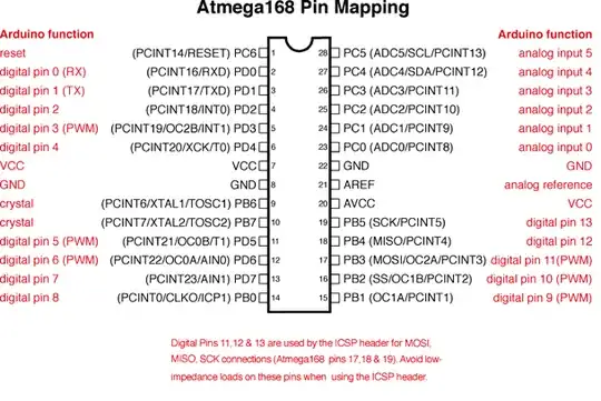
Be sure to refer to the Arduino pin mapping for help wiring this up.
- The MISO pin of your adapter will go to pin 18 or Arduino digital pin 12 of your Atmega chip.
- The SCK pin of your adapter will go to pin 19 or Arduino digital pin 13 of your Atmega chip.
- The RESET pin of your adapter will go to pin 1 of your Atmega chip.
- The MOSI pin of your adapter will go to pin 17 or Arduino digital pin 11 of your Atmega chip.
According to the pinout below, Pin 16 is SS and pin 17 is indeed MOSI.
So, to my mind, the photo is definitely wrong. Indeed I was getting avrdude errors when trying to use a USBasp to load a bootloader, when using the wiring as shown in the photo. When I correctly wired MOSI, from the adapter, to pin 17, the avrdude errors disappeared.
Am I correct in my thinking? Has anyone else attempted to build this circuit, following the instructions on the Arduino website, and come across this issue?
I am just looking for confirmation that I am right, before I contact the owner of the web page.