2

I'm trying to connect a Joystick/Encoder/Button (Copal Electronics CJ25) to a Raspberry PI. Using gpiotest I managed to get it up and running pretty well - using 3.3V input (though the data sheet mentions 5V).

The problem is, that each of the joystick's axes has 3 levels of voltage as output. 0x, 0.5x and 1x input voltage. So with 3.3V input there's 0V, ~1.7V, 3.3V.

Is there a way to simply step up/down voltage (resistors?), so that by using two different GPIOs I can detect all three states with those digital I/Os ?
ftw
  • 33
  • 5

2 Answers2

2

You MAY be able to use the Pi logic levels to detect this, but it would be unreliable. (The trigger point is ~1.3V, but varies from Pi to Pi.)

The only thing you can rely on in <0.8V => LOW; >2.0V => HIGH.

See Electrical Specifications of GPIO and https://www.raspberrypi.org/documentation/hardware/raspberrypi/gpio/README.md

An ADC would be overkill, all you need are voltage comparators - these are cheap, and available in multi comparator packages e.g. LM339 or LM393. See https://en.wikipedia.org/wiki/Comparator

Milliways
  • 62,573
  • 32
  • 113
  • 225
1

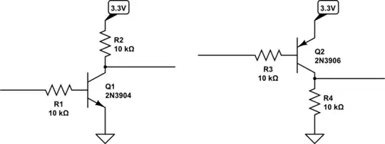
Attach level shifters with different thresholds on two GPIO pins to distinguish more than two states:

schematic

simulate this circuit – Schematic created using CircuitLab

Q1 will output 3.3V only when the input is below 0.6..0.8V, otherwise it will output 0.3V or less

Q2 will output output 0V only when the input is above 2.5..2.7V, otherwise it will output 3.3V.

Dmitry Grigoryev
  • 28,277
  • 6
  • 54
  • 147