Question
Forgive how green I am.
Use a Rpi USB to TTL cable to connect DHT22to pull data off of the sensor
Is it this simple? Most people attach it to the GPIO
Never done this before and can't find an answer elsewhere on the Net
Short Answer
No, you cannot let UART talk to DHT , because they don't speak the same language.
Long Answer
Well, one day when I was young I never followed the rules. So I did not start with connecting DHT22 to Rpi GPIO, or went the easy
way of using device tree overlays or third party python libraries.
Instead of connecting DHT22 to RpiGPIO, I connected it to one and only one MCP23017 GPIO pin, and switch input/output modes of the MCP23017 GPIO pin to talk to DHT22.
Using USB/TTL to interface DHT11 is of course simple but not possible, because their protocols are different. As I mentioned
earlier, DHT22 is using a single bidirectional wire, similar to I2C.
But DHT goes one step further and unlike I2C, it doesn't even need any clock.
UART is asynchronous does not use any clock either. But UART uses two wires
Rx, Tx. In other words, the fundamental handshaking is completely
different.
But if where there's a will there's a way. One of the many ways is
use ESP8266-12 as the middleman, something like below:
 (a) Let Rpi USB/TTL talk to the middleman ESP8266-12
 (b) Let the middleman ESP8266-12 talk to DHT22
Update 2019may06hkt0950
I am suggesting ESP8266-12/32 because it is trendy (well, for a reason), has a very small footprint, and can do WiFi. If one of your reasons using UART/RS232 is because you want long distance wired communication, in the range of 200 ft, say (me too, I am measuring the temperature of my rooftop garden, 300 ft above my bed room), then ESP8266 gives you wireless WiFi communication, over 300 meters (yes, meters). Of course Wifi ESP8266 is the way to go, with too many other reasons.
Anyway, let us come back to DHT22 and look at its handshaking protocol. The DHT22/AM2302 signal timing is very critical, as illustrated below:
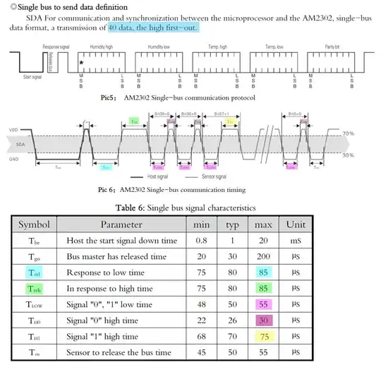
As you can see, input/output signals are time multiplexed using one single line (host and client use the same line), and what is worse, is that the signal pulses have very short, beside variable periods.
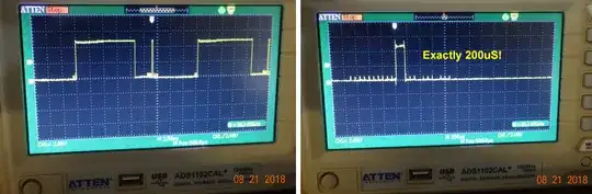
So I tried writing a python program to control one MCP23017 GPIO pin to output the DHT22 command, then (very quickly) switched to input mode to read the results. Below is the MCP23017 output, meeting the DHT22 command spec show above. Ad you can see, the pulses are so short, you need to fiddle with the I2C block write commands to meet the stringent timing requirements.
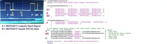
But if you go step by step, building functions level by level, from lowest, up to DHT22 command level, then you do see things "simple and easy" I also list the top level MCP23017 python function (yes, fully debugged!) to give you a rough idea of how "easy" it is to adjust, by changing a couple of numbers, the very short and variable period (in the order of 10 uS).
Rpi python 3.5.3 function to output DHT22 command pulse string from MCP23017
# *** Start Signal Part Two - 5 cycles Low, 1 cycle High, 5 cycles Low
        writeGpioOneBlock(dvNum = 0, gpioName = 'GPIOA',
                          writeByteNameList = fiveLowOneHighFiveLow)
    # *** Seven MilliSeconds Time to read data from DHT22 ***
    # *** Will Change GPIO to input mode                  ***
    writeHoldGpioOneByte(dvNum = 0, ioDirName = 'IODIRA', gpioName = 'GPIOA', \
                         writeByteName = 'AllBitsLow', \
                         holdMilliSeconds = 'SevenMilliSeconds')
return
The lower level MCP23017/DHT22 function is a bit more complicated. But once you debugged the function, you can forget all the details for good, or hide the ugly details in a protected python module, ...
Testing 4 DHT22s at the same time
In case you wonder why my DHT22 function has a dvNum = 0 parameter,
writeGpioOneBlock(dvNum = 0, gpioName = 'GPIOA', ... )
The reasons are (1) I am testing 4 DHT22s at the same time, for easy swap testing, (2) I also need to cross calibrate measurements at many places.

Advice to newbies
Though "there is a will, there is a way", you need to have a strong will, necessary prerequisite basic knowledge (UART, I2C, SPI for example) and also equipment (a US$300 digital storage oscilloscope for example), and free time (The DHT22 experiment took me more that 2 months hobbyist time, but I think it is worth it, because I learnt a lot in reading spec sheet timing diagrams and I2C communication functions.
I always remember that the Rpi is an educational tool, So I go slow to enjoy the lifelong learning journey.
Have a nice project! :)
 Please pay attention only to the sensor, which is the left hand side item.


