Question
Let me first summarize the OP's question.
He has a 220VAC water pump. He knows that a 555 IC can tell AC current on by blinking a LED. His question is how to let Rpi talk to 555 to find the pump is on or off.
Research
I am guessing how 555 detects AC current.
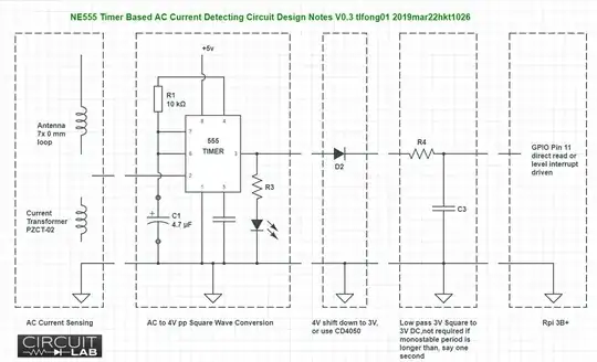
As soon as the AC current passes a wire, electromagnetic field is created. The electromagnet field induces a small 50Hz voltage/signal on the ugly looking DIY copper wire antenna which is connected to 555's trigger input.
When the AC signal is high enough, 555's monostable timer starts and stops in less than 1/50 second. The AC signal cycles every 1/50 second, so is the timer, which now outputs a 50Hz square wave signal, when water pump is switched on.
Answer
Now let me suggest a quick and dirty answer.
Let Rpi repeats reading 555 output, say 10 times, in 1/50 second, and taking the average. If water pump/current is on, the average should be somewhat high, else very low.
References
OP's Original Video Reference on 555 Timer Based AC Current Detector
https://www.youtube.com/watch?v=vp-IbQC6KK0
NE555 Timer Datasheet - Texas Instruments
http://www.ti.com/lit/ds/symlink/ne555.pdf
555 Timer Tutorial - Electronics Tutorials
https://www.electronics-tutorials.ws/waveforms/555_timer.html
555 Timer Circuits - All About Circuits
https://www.allaboutcircuits.com/textbook/experiments/chpt-8/555-ic/
ACS712 AC/DC 5A Current Sensing Module Summary
https://penzu.com/p/e0b38806
Schematic