Yes, (in general) in this case you should wire the ground terminal of all devices in your circuit together. This provides the necessary common ground reference voltage for them to interoperate.
Your voltage divider needs to go from 5 vdc to 3.3 vdc. There are two considerations in setting up a voltage divider:
a. it provides the proper voltage, and
b. its impedance doesn't interfere with proper circuit function of the interface
Here's a schematic representation of your voltage divider:
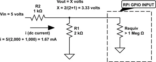
simulate this circuit – Schematic created using CircuitLab
First, we see that the output of your voltage divider is 3.33 volts, and that is "close enough" to the GPIO rating of 3.3 volts.
Second, we see that the impedance of your voltage divider will not interfere with proper circuit function. This due to the fact that the effective resistance of the RPi's GPIO input is far greater than the impedance of your voltage divider, and therefore will not place a significant additional current load on the circuit.
And so, the answer to your second question is, "Yes, you did it right."
EDIT - AN ALTERNATIVE TO THE VOLTAGE DIVIDER
I'm not changing anything in the answer above, but I wanted to add another solution - an alternative to a voltage divider. Simply replace the shunt resistor (R1 in the schematic above) with a 3.3V Zener Diode. as shown in the schematic below. The motivation for using a Zener instead of a voltage divider is that it will provide a more stable 3.3V input voltage to the RPi. Specifically:
In situations where the external voltage is unknown, or fluctuates over a wide range, the Zener diode will hold the input voltage to the GPIO pin at a steady 3.3V. Here's an example: Assume for a moment that something went wrong, and the external voltage was 9V instead of 5V. In this case, the voltage divider would put 6V at the RPi GPIO pin, possibly damaging the RPi. However, the same 9V external voltage applied to the Zener circuit below would continue to present 3.3V to the RPi GPIO pin.
While the GPIO pins on the RPi have a high input impedance, this is not true of all inputs. Zeners offer an advantage in interfacing with such low impedance circuitry because their output voltage is unaffected (within reasonable limits) by current flowing through the series resistor (R2 above).
A bit obscure, but some sensors behave more as a current source than a voltage source. Some circuit examples of current sources. The Zener circuit below will keep the voltage at the GPIO pin of the RPi at 3.3V over a wide range of current.
And so, Zener diodes offer advantages over a voltage divider. Zener diodes are also inexpensive and plentiful; here's a list of 3.3 V Zeners from a vendor I use. (Disclaimer: I have no affiliation w/ Mouser)
Here's a schematic showing use of a Zener diode instead of the voltage divider:
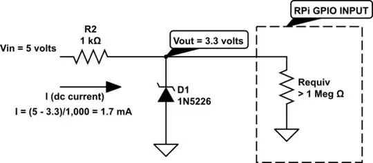
simulate this circuit
The 1N5226 Zener is rated at 0.5 watts. If we allow it to dissipate 0.1 watts, this circuit will provide 3.3V at the input to the RPi's GPIO pin for Vin up to 90V.
Note however that while a 90V input won't over-stress the Zener in this circuit, it will create a voltage drop of 86.7V across R2, and R2 will need to be sized to dissipate approx 1.6W.

