TL/DR: I’m using this and there are things I don’t understand about this circuit. Ultimately I’d like to read data from this sensor, but all I get is gibberish. Please, help.
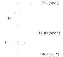
I have set up “poor man’s a/d” adapter as described here. In my case it looks like this:
My code for retrieving and visualising data looks as follow:
#!/usr/bin/env python

import time
import datetime
import numpy as np
import matplotlib.pyplot as plt
import warnings
from collections import deque
import RPi.GPIO as GPIO
import time
GPIO.setmode(GPIO.BCM)


warnings.filterwarnings("ignore",".*GUI is implemented.*")
the_file = open('data.txt','w')

# class that holds analog data for N samples
class GPIOData:
  # constr
  def __init__(self, maxLen):
    self.ax = deque([0.0]*maxLen)
    self.ay = deque([0.0]*maxLen)
    self.at = deque([datetime.datetime.utcnow() + + datetime.timedelta(seconds=i) for i in range(maxLen)])
    self.maxLen = maxLen

  # ring buffer
  def addToBuf(self, buf, val):
    if len(buf) < self.maxLen:
      buf.append(val)
    else:
      buf.popleft()
      buf.append(val)

  # add data
  def add(self, data):
    assert(len(data) == 3)
    self.addToBuf(self.ax, data[0])
    self.addToBuf(self.ay, data[1])
    self.addToBuf(self.at, data[2])

# plot class
class GPIOPlot:
  # constr
  def __init__(self, GPIOData):
    # set plot to animated
    plt.ion()

    fig = plt.figure()
    fig.suptitle('Values from pin', fontsize=10)
    plt.xlabel('Time', fontsize=9)
    plt.ylabel('Values', fontsize=9)
    self.axline, = plt.plot(GPIOData.at,GPIOData.ax)
    self.ayline, = plt.plot_date(GPIOData.at,GPIOData.ay)
    #plt.ylim([0, 1023])

  # update plot
  def update(self, GPIOData):
    self.axline.set_ydata(GPIOData.ax)
    self.ayline.set_ydata(GPIOData.ay)
    self.axline.set_xdata(GPIOData.at)
    self.ayline.set_xdata(GPIOData.at)
    #plt.plot.set_xdata(analogData.at)
    #plt.gcf().autofmt_xdate()
    plt.draw()


# Define function to measure charge time
def RC_Analog (Pin):
  counter = 0
  # Discharge capacitor
  GPIO.setup(Pin, GPIO.OUT)
  GPIO.output(Pin, GPIO.LOW)
  time.sleep(0.2)
  GPIO.setup(Pin, GPIO.IN)
  # Count loops until voltage across capacitor reads high on GPIO
  while(GPIO.input(Pin)==GPIO.LOW):
        counter =counter+1
  return counter


DataPts = 50
TotPts=10000
gpioData = GPIOData(DataPts)
gpioPlot = GPIOPlot(gpioData)

Pin = 17

for counter in range (TotPts):
    time.sleep(0.1)
    out=RC_Analog(17)
    if out < 2000:
      print out
      tm = datetime.datetime.utcnow()
      counter = counter+1
      gpioData.add([float(out),float(out),tm])
      gpioPlot.update(gpioData)
      plt.axis([min(gpioData.at), max(gpioData.at),0,max(gpioData.ay)])
      plt.pause(0.05)


while True:
    try:
        plt.pause(0.05)
    except KeyboardInterrupt:
        print('exiting')
        break

the_file.close
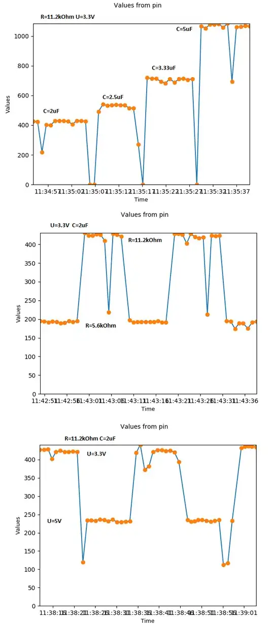
In brief, in order to convert analog signal to something digital capacitors are introduced to circuit. They are discharged by setting GPIO to OUT and LOW. Next, pin is set to IN and script counts time needed to charge capacitors enough to be read as HIGH. Original post suggest that it may be used to measure changing R values, but I have realized, that one can actually measure resistance, capacity or power input:
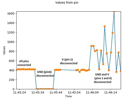
So far so good: behavior that we'd expect from this circuit. However strange things happen when I disconnect pins:
In my understunding : When GND is disconnected, meaning capacitors are not in the circuit, power rises so quickly, so that counter value is 0.
When power is disconnected voltage on capacitors never rises to level recognised by GPIO as HIGH until this pin is reconnected so data points are totally omitted. (there actually should be point with huge value corresponding roughly to time between disconnecting and reconnecting this pin, it is filtered out in line “if out < 2000:”)
Q1: But, what happens when both pins are disconnected? How come there is anything happening? Why this is so chaotic?
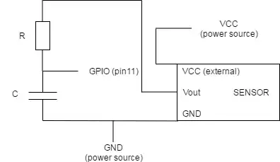
Ultimately I’d like to read signal from this sensor. This is circuit I use:
As you can see tt is powered from external source. I’ve checked with multimeter, that signal (Vout) is in the range of 3.1V. When I connect it this way result is as if both pins 1 and 6 were disconnected – noisy signal witch very high and very low inconsistent values.
Q2: Is this setup appropriate for measurement of with aforementioned sensor?
Additional Info: RasPi3 Model B, Python 2.7
EDIT: ADDED MISSING LINKS.


