Final edit: Got it working! Thank you all for your suggestions.
The first issue was that my magnet was broken. I got a multimeter and tested the switch open and closed, and the meter was detecting current regardless of the state.
I bought a new switch and it works as intended. (current stopped, current flowing)
The second issue was in my code. I was reading the GPIO status outside of the while Loop.
In the end, I learned some valuable information. Thank you all!
I'm using a 2.5A Canakit power supply to power the Pi.
Since I need the magnet switch, how can I use an external DC power supply to send power to the magnet?
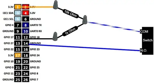
If I use 3.3v or 5v, like the diagram suggests, my Pi's LEDs dim. This is because I have a Sharp IR sensor and a Pi camera connected already. Not enough juice I guess.
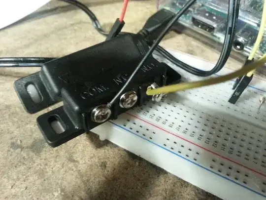
This is how I currently have the magnet switch hooked up:

Thank you!
EDIT:
I'm using a magnet switch. Sorry for calling it a relay.

EDIT 2: @Joan suggested using GPIO to NO and GND to COM. I did that but there were no status changes if the switch was on or off according to the Pi.
EDIT 3: Here's my code. Am I enabling the internal resistor?
import RPi.GPIO as GPIO
GPIO.setmode(GPIO.BCM)
GPIO.setwarnings(False)

GPIO.setup(22, GPIO.IN, GPIO.PUD_UP)

read = GPIO.input(22)

while True:
    if read == True:
        print ('Door is True')
    else:
        print ('Door is false')
