The problem
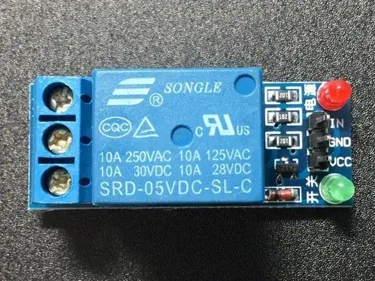
The problem is that your relay board is designed to run at 5V, but your Pi's GPIO is 3.3V. The relay is a 5V relay, so the power supply needs to be 5V, but you can alter the design of the driver board slightly to make it work at 3.3V input. Looking at this image, we can clearly see the transistor is marked 2TY which means it's an S8550 PNP transistor, and the resistors are all marked "102" which means they're 1K ohm resistors. Also, although I don't read Chinese, Google translate helpfully tells me that 开关 near the green LED means "switch" and 电源 near the red LED means "power supply" so we can infer that the red LED will be on whenever this board is powered, and the green LED will probably toggle with the state of the input pin.
From that, it's pretty simple to draw a schematic:
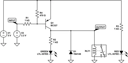
simulate this circuit – Schematic created using CircuitLab
Note that without R4 (which is what you have), we get a voltage output like this:

As you can see, nothing happens until the input voltage rises above 4.1V which is higher than your Pi can manage. The PNP transistor is only forward biased (conducting) when the base voltage is around 0.7V lower than the emitter voltage, or about 4.3V. The Pi's GPIO is only 3.3V.
A bad solution (do NOT do this!)
If you add the 470 ohm resistor R4, and you'll get a voltage plot like this instead:

Now the relay's state changes when the output voltage rises above about 2.6V. Problem solved? No! I'm embarrassed to say that was the "solution" I had originally posted, because I was only thinking about properly biasing the PNP transistor, but as @Milliways correctly pointed out, this will likely be fatal to the Pi. Let's analyze why and come up with a real solution.
Pi GPIO
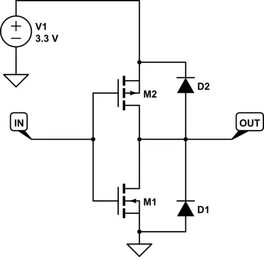
The GPIO pins on the Pi, like most processors, can be thought of as a pair of FETs and a pair of diodes something like this:
simulate this circuit
The complementary FETs M1 and M2 provide the 0 or 3.3V output and protection diodes D1 and D2 protect against brief excursions on the pin of less than 0V or greater than 3.3V. However, these protection diodes are not terribly robust and are not intended to remain on (forward biased) and conducting for any length of time (think milliseconds). If they are forward biased for a longer period, with a current of, say 1mA or more, the device will overheat and be destroyed, rendering your Pi partially non-functional at best, or completely dead at worst.
If we look at the relay circuit above we see that from +5V through resistor R4 (470 ohms) and R1 (1k ohm) goes straight into the pin. Because 5V > 3.3V the protection diode will be forward biased and will be conducting and heating the part. The current would be about (5 - 3.3)/(470 + 1000) = 1.2mA which is higher than would be safe. The other suggestion originally posted was replace R1 with a 2.2K part and apply R4 with 680 ohms. That would result in (5 - 3.3)/(680 + 2200) = 0.6mA which might be low enough to be safe, but it's not the best possible design.
A real solution
There are a number of safer alternatives. The simplest would be to simply replace the relay, which is an SRD-05VDC-SL-C with a drop-in replacement SRD-03VDC-SL-C (see http://www.mouser.com/ds/2/321/27115-Single-Relay-Board-Datasheet-709206.pdf for datasheet). Then use 3.3V supply as Vcc for the relay board.
Another is to use a different transistor. Recall that using a PNP transistor means that to turn the transistor on, we need to have a VBE (voltage from base to emitter) of around -0.7V. With an NPN transistor, it's the same but with the polarity reversed, so around +0.7V. This brings the voltage well within the 3.3V range of the Pi and could be done like this:
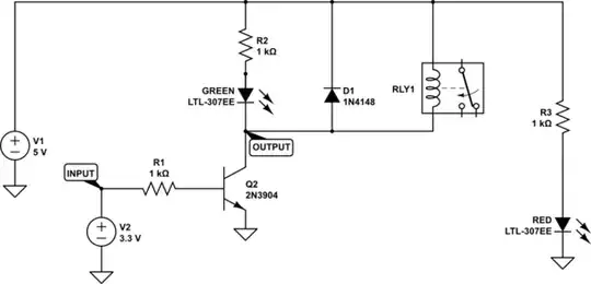
simulate this circuit
About current
With this circuit, GPIO pin current will be about 2mA. If I'm not mistaken, the GPIO pins are set by default to source 2mA, so no change is required using the latter circuit. The Pi's GPIO pins can source up to 16mA, but they should not be asked to source more current than they're programmed for to avoid damage.
Also, the entire relay circuit will draw about 80mA from the 5V power supply. The onboard 5V supply should be more than adequate for this.
Acknowledgement
First, apologies for my original answer which was not good. Second, thanks to @Milliways for pointing that out. I'm hoping that by showing both the bad solution, analyzing it, and showing real solutions, that others may learn from my error.


