I have the following on-off-on-off button that I purchased from Adafruit for use with my Raspberry Pi 1 Model A.
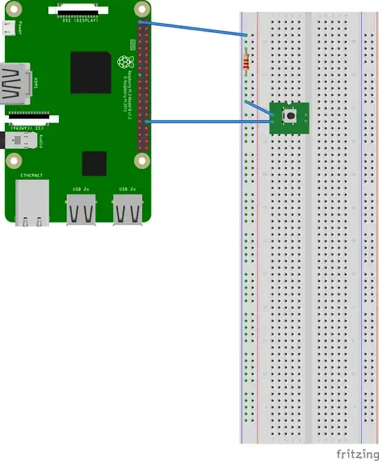
I'm trying to "bypass" the "on-off-on-off" functionality, and just make it so that its an "on-off" switch/pushbutton. I believe the wiring setup that I'm looking for is:
Where I'm:
- Connecting the RPi's 3.3V power supply to the middle pin of my pushbutton (with a 10kOhm resistor in between them); then
- Wiring the two outer pins (left and right) together and attaching them to the GPIO input pin
Can anyone confirm I have the wiring correct? Or is it the opposite (where the outer two pins go to GPIO instead of GND, and the middle pin goes to GND)? Or is the solution something completely different?
Again, the ultimate goal here is to be able to push the button once, and send an input signal to the GPIO pin. Push the button a seconnd time, and the circuit disconnect (we stop sending input signals to the GPIO pin). Push it a 3rd time, and we're right back to the beginning (sending an input signal), etc.
