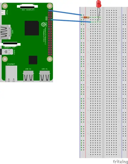
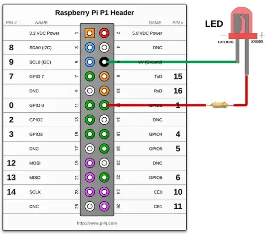
I have a Raspberry Pi 1 Model A and am trying to control an LED from an app that I will be running on it. The wiring I'm planning on going with is:
Even though thats a RPI 3 in the diagram above, the concept is the same:
- Connect the RPi to a suitable power source (via Micro USB)
- Connect the 3.3V pin on the RPi to the power rail on the breadboard
- Connect the column where the LED (1.2V @ 100mA) will be placed to power through a resistor (47 ohm)
- Then just connect the column where the LED's 2nd leg is located back to a GPIO pin that is configured to be an output pin
So I wanted to verify (I'm afraid I'm going to fry my pi!):
- That the wiring is correct; and
- That I'm using the correct resistor to do the job (R = V/I = (3.3V - 1.2V)/.1A = 2.1V / .1A = 21 ohms...so I figured 47 ohms is OK); and
- That I should be configuring my GPIO pin to be on output pin afterall
Thanks!

