1

Raspberry Pi 1 Model A here.

I am planning on using this pushbutton in a hobby project that is very similar to this CamJam EduKit project.

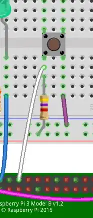
In that CamJam project link, on page 2, I see a simple wiring diagram where it shows how to wire up the pushbutton:

enter image description here

If I'm looking at this correctly:

  • It appears that I place a resistor in between the voltage source and the pushbutton's PWR pin
  • It appears that I place a GPIO output pin in between this resistor and the pushbutton's PWR pin

If these assumptions are true, then I have a few concerns:

  • With LEDs, you usually put the resistor in between the LED's GND pin and the GND, so why is it the opposite with pushbuttons (putting the resistor on the "inbound"/PWR side, rather than the "outbound"/GND side)?; and
  • My pushbutton has 3 pins; I assume 1 is PWR and 1 is GND, but what's the 3rd? And how do I figure out which pin is which?
  • I assume that the calculation for the resistor is the same with pushbuttons as it is for LEDs. That is, the GPIO output pin is yielding 3.3V of voltage, the pushbutton is rated at 12V @ .5A, so this is 3.3V - 12V = -8.7V (maybe this is why the resistor goes on the PWR/incoming side?!). 8.7V / .5A = 17 ohm resistor? Am I doing that right?

Thanks in advance for any and all help!
smeeb
  • 645
  • 3
  • 9
  • 22

2 Answers2

2

You seem to have several misconceptions going into the question, so let me start with those:

  • You can put the resistor on either leg of an LED in general, as long as they are in series. I'm not sure why you think otherwise.
  • In a closed loop, the total resistance along the loop determines the current. For both the switch and the LED the resistor is there to limit current.

Now regarding your interpretation of the diagram, both points that you give reflect what's shown.

Regarding your specific questions:

  • For input pins, you can have them trigger when they are high or when they are low. This set-up is for the pin to register "pressed" as low. The resistor that concerns you is a "pull-up" to high that keeps the pin high when the switch is open. When the switch is closed there's a resistance-free path to ground, so the pin will see "low".
  • Your push button is really two switches in one. Read the description at the link you gave. It tells why there are three pins and what they do. It's pretty specific.
  • There's some art to choosing pull-up resistor values. Roughly you want to choose them "large" so that you don't draw a lot of unnecessary current, but not "too large" so that they don't actually pull. There's a ton of information on this if you search for "pull-up resistor" and/or its dual "pull-down resistor." You're probably safe in this case using one close to what's shown in your tutorial.
Brick
  • 1,375
  • 2
  • 14
  • 20
2

I assume that the calculation for the resistor is the same with pushbuttons as it is for LEDs.

Your assumption is mixing input and output.

I have just explained what the difference between input and output is here:

RPi 1 Model A input/output pin ratings

And the reason for a pull-up/pull-down is that a GPIO pin without these can be in an "unknown state" aka floating and pick up static charges and behave erratic.

So a pull-up/pull-down resistor is forcing the input to always be in a known state!

MatsK
  • 2,882
  • 3
  • 17
  • 22