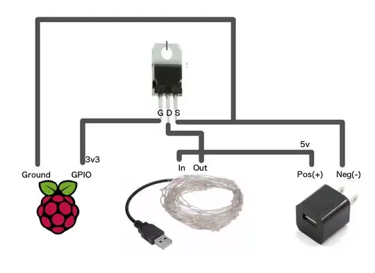
Do not put the resistor between gate and source when using a N-Channel MOSFET, that is wrongly given in a lot of places on the web. But why; it reduces the drive to the gate of the MOSFET by dividing the gate drive voltage. With a pi and 3V3 your choices are very limited on parts to start with, however it is getting better. You need a MOSFET that turns on at about 2V or less so it is reasonably well enhanced at 3V3. The pull down resistor should go to the port pin and ground not the gate and ground.
The reason for this resistor is most microprocessors/computers have there outputs tristated until they get initialized and the output set to the proper point. During this time the port pin can drift wherever and turn the MOSFET on, sometimes partially destroying it. This generally is not wanted. If you want it on then pull the port pin up to 3V3 otherwise use a pull down from the port to ground.If you put a 10K pull down at the gate and a 1K from the port you now have 3.0 volts on the gate, not 3V3. I use something between 25 and 50 ohms to keep the gate drive solid.
I can understand the confusion. First and most important thing about MOSFETs is all voltage reference points are to the source. Normally P-Channel is for Positive switching and N-Channel is for negative switching. To turn on a MOSFET you see such things as Vgs. This is (Voltage Gate Source) It is positive for N-Channel devices and negative for P-Channel devices. The gates have a maximum Plus and minus rating, anything in that range referencing the source if fine.
Lets try this, your circuit shows a MOSFET where the Pi gives it voltage from the port pin. The source is connected to ground of the PI and its external power supply, this is correct. When you turn the port pin on it will place 3V3 on the gate. If it is not sensitive in that area (Vgs) to high it will not turn on, that is the way it was designed. If say it needs 2V it will turn AOK. Note we are referencing the ground (source) for these voltages.
Now the same thing with a P-Channel MOSFET. In this case the source is connected to +. If the previous holds true you need a negative voltage to turn it on. First thought now I need another supply, not true. Remember the source reference, guess what the ground is - in reference to the source so it will turn on if the gate is grounded.
When you purchase MOSFETs get the ones that are rated for avalanche energy. They are designed to conduct a lot of current for a short period of time. When you switch an inductor on you store energy in the coil, when you turn it off that energy comes out as voltage. But it does a funny thing it changes polarity and will rise until something stops it (Ignition coil). Two common approaches is to place a diode across the solenoid to dissipate the energy (it needs to be rated to handle the coil flyback current). The diode will turn on and limit the voltage to about -0.7V until the energy is dissipated. This is a short high current pulse. An avalanche rated MOSFET by its very geometry has a substrate diode (it is shown in the simble) that happens to point in the correct direction. This will behave like a flyback diode but it is resistive in nature so the flyback voltage can vary. I use the RDSon x 2 when calculating the current and voltage.
Hopefully this helps you understand what is happening. They are great parts if used properly.
