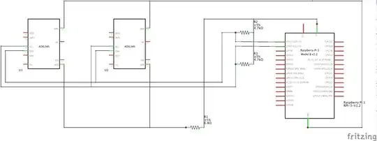
I am new to electronics, and I have been playing around with Raspberry Pi 3 and an ADXL accelerometer. So far, I have managed to draw data in I2C from the accelerometer. However, now I am trying to draw a schematic for a prototype with two ADXL accelerometers. I have made an attempt, but since I am new to this, I have no idea whether I am on the right track. Here's what I've put together. In particular, I am not sure about the pullup resistors. Also, do I need to connect CS?(many of the online tutorials do not mention it).
2 Answers
A common mistake in electronics is using a resistor as a voltage regulator. I'm talking about R1 which you seem to include to reduce the voltage from 5V to 3.3V needed by the accelerometers. This will not work, and almost certainly damage the ADXL345 chips.
Instead, you should power your accelerometers from the 3.3V pin, and you need to connect both VDD and VS pins of each chip to 3.3V line.
As a consequence of this change, your pullup resistors should also be connected to the 3.3V line.
Regarding CS, you only need to connect it when using SPI.
- 28,277
- 6
- 54
- 147
If you are using I2C you must ensure the ADXL345 modules have different addresses on the bus.
Does your module provide a way of setting the address?
The documentation for the module you are using should say. The underlying ADXL345 chip has provision to set two different addresses although this capability is not necessarily brought out on all modules.
If you used SPI instead you would use a different GPIO connected to the CS signal to select the ADXL345 module.
- 71,852
- 5
- 76
- 108
