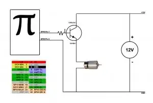
So, I have a thesis to do where I need to use a Raspberry Pi 3 model B. In the Raspberry Pi, I will need to run a Matlab/Simulink simulation that will give me some results as output. Then I need to take that output and program some kind of PLC, that will communicate with another board using the GPIO output of my Raspberry Pi 3.
My schematic is this: https://i.sstatic.net/mI9Ka.jpg
My Raspberry Pi 3 will work as the ripple control receiver in the image. It will work like this: I have 4 digital outputs (D1, D2, D3, D4) that will give me 16 combinations. It will be 1 of that 16 combinations that will be sent to the module on the right (depending on my Matlab/Simulink results).
The problem is that in the port 5, the module is powered up with +12V, and the Raspberry Pi 3 GPIO only supplies 5V. So I will need some kind of converter or relay that will boost my voltage and also feed the other 4 ports (when the respective "switch" is ON, like in the worst case where all the "switch" gates are ON).
So can you guys help me?
