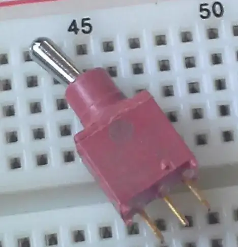
This is a two state system -- the switch is either to the left or to the right. Since there are three pins, and presuming two of them are not hardwired together, this means the switch position determines which two pins are connected, and that one of the pins is always connected to another one. You want to determine which of the three pins that is -- I'll call it pin X.
Connect it up as follows:
One pin to a GPIO that will be an output driven high (or just a 3.3V rail pin, which makes it easier). I'll call this the source pin.
The other pins should be connected to GPIOs set as inputs (this is the default). On the breadboard channel between the pin and the GPIO, connect a largish resistor (10K ohms) to ground (i.e., a pull-down). This ensures the GPIO will read low when disconnected from anything, and if the source pin connects to it, current will go to ground through the resistor, protecting from a short circuit, and the pin will read high.
I'll call these pins A & B.
Wired up that way, there is nothing you can do that will cause any damage except accidentally set one of the inputs as an output, which could cause a potential short. However, you'd actively have to do that, since the default for GPIOs that don't have another purpose is as an input. So make sure you use two of those (17, 22, 27, etc).
This guarantee of safety covers the possibility that two of the pins are hardwired together, or even all three of them (which would make it a bit of a joke switch, of course).
Again, there are three possible outcomes here that can be summarized in three tables, but two of them are the same with the rows switched, so I'll only type it out once:
Switch:        Left    Right

Input A:       Low     Low

Input B:       High    Low
The source pin isn't referred to because nothing about it changes. It's just a +3.3V source. The switch has two positions, and the inputs have two possible states when read.
If the outcome looks like this, it means that Input B is pin X. If it's the other way around (i.e., B is always low and A changes state with the switch), then Input A is pin X.
From this you can also deduce what X connects to in each position. Following the table, when the switch is left, it is connected to the source pin. When the switch is right, it is connected to Input A.
The third possibility is that the source pin is pin X. The table will then look like this:
Switch:        Left    Right

Input A:       High    Low

Input B:       Low     High
In this case, when the switch is left, X connects to Input A. When it is right, it connects to Input B.
If you get something different from this -- one pin is always high and the other always low, or both always high, or both high and low at the same time -- then two of the pins are wired together. There are still three possibilities for pin X corresponding to these three alternate possibilities.
