4

I'm (now for some weeks) trying to get a thermal printer (ttl) to work without success. I've done every step exactly like said in this tutorial but the printer does nothing. Since I don't know how to debug this kind of problem and I also couldn't find any solutions on the web, I hope you can help.

The Hardware:

  • RPI2 B
  • Thermal Printer - Adafruit #597
  • Power supply for the RPI 5V 2.5A
  • Power supply for the printer 5V 10A

The Software:

  • Raspbian Jessie
  • Zijiang ZJ-58 Printer Driver
  • Different Packages (see tutorial)

EDIT

ls -la /dev/ttyAMA0 results in crw-rw---- 1 root dialout 204, 64 Jul 27 10:47 /dev/ttyAMA0

sudo echo "TEST" > /dev/AMA0 has absolutely no effect.


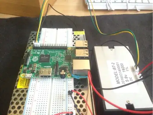
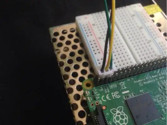
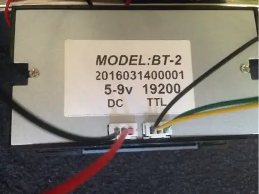
Here are the wires:

overview connection to rpi connection to printer


UPDATE

Now It's connected correctly but still isn't reacting to sudo echo "TEST" > /dev/AMA0. I think there is nothing broken, because if i boot with serial port enabled, the printer starts to print endless gibberish stuff.

Any idea?

I've just erased the raspbian and started from scratch.

  1. Start up and disable Serial => done
  2. Restart => done
  3. Connect the printer => done
  4. Substitute the correct baud rate via stty -F /dev/ttyAMA0 19200 => done
  5. Print test echo -e "This is a test.\\n\\n\\n" > /dev/ttyAMA0 => nothing happens

1 Answers1

3

The connector on the pi is in the wrong position. It's starting at the second pin down on the outer row, which is a 5V power pin, so the other two pins connected to the TTL jack on the printer are GND and TXD.

Presuming the black wire is for ground and that cable was built to cross the lines properly (it is impossible to tell which pin is which on the printer, but the jack seems to fit in only one way, so if it came supplied from Adafruit it should be correct), then you want to move it one pin down, so there are two pins above it (considering the short end of the board with the USB & ethernet jacks as "below").

If you look at the full size image from the Adafruit guide this is easier to see (also there are lots of diagrams of the breakout online explaining what each pin is; going by that one you wanted pins 6, 8, and 10, not 4, 6, and 8).

Since the pi is still running I don't think accidentally attaching 5V to the ground of the printer will have damaged anything (although see ppumkin's comment below for a more refined opinion about that); I think it would have effectively disabled the serial connection. The major risk here would be shorting the 5V to ground, but if that happened the pi would be junk now.

However, since this means they were connected TX to TX, if the printer did output a wacky signal voltage then the UART may be damaged. If you connect it properly and it works, then no harm was done. Again presuming the cable crosses over properly, the middle wire yellow wire would have been from the Pi's GND to the printer's RX, and that is harmless (it also means the printer's RX line would never have gone high, so chances are it did not even consider there to be any connection on the TTL port).

goldilocks
  • 60,325
  • 17
  • 117
  • 234