5

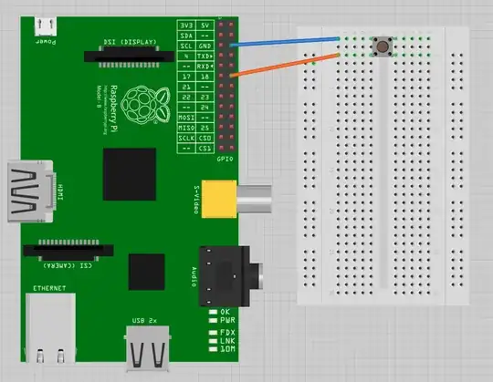
I saw a tutorial here that shows wiring a button without a resistor. I have heard that this is bad if you set the pin as an output by mistake and press the button because it shorts the pin to ground.

Besides that issue, can this be done with multiple buttons as long as I make sure to code it correctly? I read somewhere else that this only works with the I2C pins and thus can only work with a maximum of 2 buttons.

I am working with a Raspberry Pi b+, but I also have a Pi 3 available.

enter image description here

NULL
  • 2,240
  • 8
  • 28
  • 49

2 Answers2

5

If the code is written correctly such that the GPIO pins are input only, you should not have an issue. However, the use of resistors may still be warranted ... but not to limit the current in case of bad coding but instead to pull the default state of a button to a logic level. When the button is "up", it is effectively an open circuit. What then is the logic level on the GPIO? If you don't have pull-up or pull-down resistors, then the logic level will "float" and you could have un-expected results which appear to be button presses when no button is pressed. You can code around that with the PI's logical pull-up and pull-down resistors. I believe the GPIOs allow us to say that a pin is input and should have a pull-up or pull-down resistor (logically) attached. I am guessing that in the circuitry there is the ability to engage internal resistors to achieve that capability.

Kolban
  • 1,794
  • 2
  • 16
  • 28
3

I know it's an old question, but I've been reading into the RPi's internal resistors. I'm hoping to use them in order to make my circuit a little bit simpler.

According to this answer there are pull up/down resistors on all of the GPIO pins on the Raspberry Pi B+ and later.

The circuit and program in the tutorial uses an internal pull-up resistor on an input pin. This means current is constantly supplied from the resistor which sets the open circuit to a logical HIGH. When the switch is engaged, it grounds the pull-up voltage which drops the circuit to a logical LOW. This is the opposite logical sequence to what most other circuits use where their buttons switch on the voltage, not the ground.

Tutorial (Button on GND):
HIGH: Open Circuit
 LOW: Closed Circuit

Typical (Button on 3V3):
HIGH: Closed Circuit
 LOW: Open Circuit

Now that being said, for the purposes of safety, I would still recommend a small resistor between the switch and pin if you can't be 100% confident in the software. Just in case the pin gets set to output, the resistor will be there to not let it short circuit to GND.
flamewave000
  • 141
  • 3