4

I would like to run a the LD1117H linear 3.3V regulator on my Pi's 5V rail in order to provide more current than the 50mA that the onboard 3.3V rail provides. My concern is that this is not entirely safe when using the externally regulated 3.3V for operations involving the Pi's internally regulated pins.

General information:
I have a device (U1) which may draw more than 50mA and will produce an analog output I want to read with an analog to digital converter. I believe the ADC must use 3.3V as its Vcc to properly communicate with the Pi via I2C or SPI; therefore, ADC input should not exceed 3.3V. Apparently, the Pi's 3.3V rail can't (or shouldn't) source more than 50mA of current, therefore I must use a linear voltage regulator with the 5V rail.

Questions:
Is using the Pi's GPIO pin on Q1 potentially dangerous? Is using the external regulator to power the ADC that will send I2C/SPI to the PI potentially dangerous? The voltages should be very close to each other but there is something about mixing the voltages coming from two regulators (the Pi's internal regulator and the LD1117H) that is bothering me.

Note: Some resistors/capacitors unessential to the question were omitted from this schematic for simplicity.

schematic

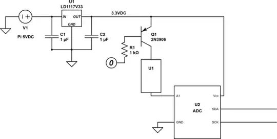
simulate this circuit – Schematic created using CircuitLab

John P.
  • 170
  • 1
  • 8

2 Answers2

4

Apparently, the Pi's 3.3V rail can't (or shouldn't) source more than 50mA of current

I'm shamelessly taking this from a recent Piversify post, "Exploring the 3.3V Power Rail", by one of our other members. The focus there is on the B+ but as Milliways points out should apply equally well to the Pi 2, since it would be a little bizarre to have moved backward with the technology.

...the 5V rail provides power to the on-board buck converter.

The buck converter (Richtek RT8020) supplies power to the 3.3V rail. The primary job of the 3.3V rail is to power the SoC processor and GPIO. The 3.3V rail also offers surplus power which can supply external sensors and devices. For clarity, I should emphasize the surplus power I’m referring to is supplied from the 3.3V power pins on the GPIO, not the larger set of I/O pins on the GPIO that are dedicated to digital signal processing, an entirely different topic.

The surplus power from the 3.3V rail is more limited than what the 5V rail can deliver. We can estimate 3.3V surplus power by taking the rating of the converter (1A, per spec) and subtracting the load required by essential power consumers like the SoC and any GPIO signal connections.

There is also a "Load Regulation Test" graph there demonstrating that the 3.3V rail is soundly regulated under load up to 800 mA, leaving 200 mA for the idling SoC.

So I do not think the 50 mA figured tossed around WRT pre +/2 models applies,1 and you should have ample power for your ADC. Based on the above information and tests, and assuming the quad core Pi 2 SoC draws <500 mA when under load, you still, conservatively, have at least 3-400 mA to play with safely.


1. In fact I think that figure is certainly way too low as well. I believe it refers to the combined load recommended be placed on the GPIO outputs, and not the rail from which the dedicated 3.3V pins are powered.

goldilocks
  • 60,325
  • 17
  • 117
  • 234
2

You raise several issues:-

  1. The Pi 3.3V rail is widely assumed to provide 50mA, but AFAIK this is not officially documented for the Pi2 or the other recent Pi. The original Pi has an on-board linear regulator which was limited, but the B+ and later have a switch mode regulator which may well supply more. The regulator chip (which supplies both 3.3V and 1.8V is rated at 1A). I haven't tested this, but you could give it a try.

  2. You can use 5V with the ADC and safely interface I²C to the Pi, provided you use the on-board pullup to 3.3V. To use SPI you may want to use the inexpensive level converters which are probably less costly than the regulator.

  3. The risk to the Pi of providing more than 3.3V is greatly overrated. Provide this does not exceed 3.3V by more than a diode forward drop and limit the current with a series resistor this should be quite safe, and you could be doubly sure by including a clamp diode to the 3.3V rail. I doubt the ADC could provide enough current on digital pins to cause any damage.

You should certainly should NOT connect the output of a 3.3V linear regulator to the supply rail, but I don't think you were suggesting this.

Milliways
  • 62,573
  • 32
  • 113
  • 225