I've built a simple joystick for my RasPi 3 Model B. When making it, I tried to minimize the number of its GPIO pins, and ended up with a design that uses 3 pins.
However, I'm afraid I'm about to put lot of strain on my Pi here. For example, the buttons on my joystick look like this:
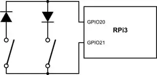
simulate this circuit – Schematic created using CircuitLab
(No, I didn't solder it on the headers, I just picked these two pins for the sake of argument.)
When reading the state of the buttons, the driver would first put GPIO20 to read mode, then put GPIO21 to write mode and write a 1. Then, digitalReading GPIO20 would tell us if the left button is pressed. For the right button, we can do the same thing in the other direction.
What I'm concerned about is that this program would toggle the mode of GPIO20 and 21 between Read and Write about a hundred times per second. I have never seen a protocol that uses the same pin for reading and writing, which makes me think it is bad practice, and possibly, at this frequency, even harmful to the CPU.
Is my joystick indeed dangerous? If I were to use it regularly, as a mouse, would it do a considerably greater damage to the Pi than, say, a normal USB mouse?
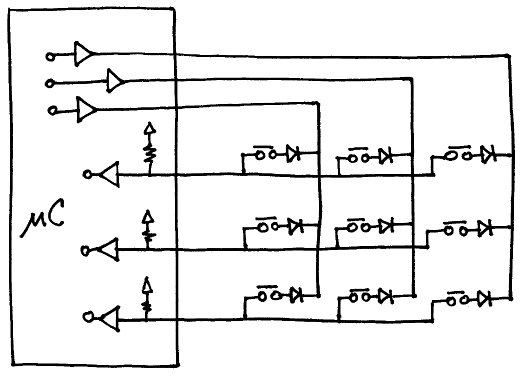
EDIT: As noted in the answers, this kind of wiring is an unreasonable effort to save a ground wire. I chose this approach mainly because it can handle n*(n-1) switches with n pins, by covering all the possible directions from one pin to another with a diode and a switch. My joystick has 6 switches (two buttons and a 4-direction stick), thus requiring 3 pins (as opposed to the 7 pins called for by the 'normal' approach). I didn't post the full schematic because I tried to keep it simple.