3

enter image description here

I am having trouble with a dht22 sensor. It works well for most of the time but randomly the library I am using can no longer receive a reading until I unplug then plug the sensor back in. (just disconnecting and reconnecting the GND pin is often enough) Then it will work for a while longer until the problem repeats.

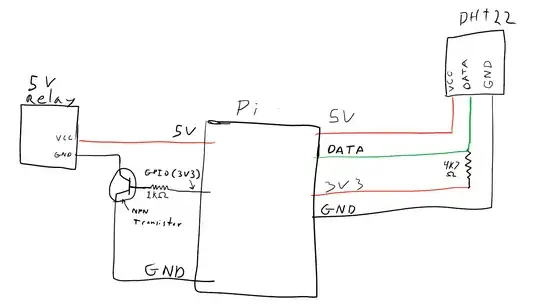
I will try to describe my setup pictured in the drawing above in detail. The picture above is not a proper diagram drawing so please ask any questions if my text description falls short as well...

The DHT22 hookup is pretty straight forward 5V to VCC pin, GND pin to ground, DATA pin to a GPIO pin (GPIO 24 in my case). I am pulling up the DATA to 3V3 with a 4.7K Ohm resistor. I am using the pgpio DHT22 library. Here is the code which involve a loop in order to ignore the first couple of "bad" readings from the DHT22. (the DHT22 always gives the first two or three reading for temp and humidity as -999) also An important note is I am using about 10 feet of cat5e cable to connect the sensor directly to the pi.

#!/usr/bin/python
import pigpio
import DHT22
from time import sleep

# initiate GPIO for pigpio
pi = pigpio.pi()
dht22 = DHT22.sensor(pi, 24) 

def readDHT22():
    #get reading
    dht22.trigger()
    humidity = '%.2f' % (dht22.humidity())
    temp = '%.2f' % (dht22.temperature())
    return (humidity, temp)

r = 0

while r < 10:
    humidity, temp = readDHT22()
    print ("trying to read temp...")
    r = r + 1
    if '999' in humidity or '999' in temp:
            sleep(sleeptime)
            continue
    sleep(sleeptime)
    print ("H:"+humidity+"")
    print ("T:"+temp+"")
    sleep(2)
    break

The other part of my diagram shows the connection for a 5V relay. There is actually 5 relays connected. they each share a 5V rail and a Ground rail. Each relay has its own GPIO connection used to send a HIGH signal to a transistor that acts as a switch for the relay.

The reason I mention the relays in my problem is I suspect that my issue could be that I am drawing to much current from the pi.

What basic steps should I take to begin trouble shooting an issue like this?

How can I accurately calculate the amperage of my circuit to determine if I am drawing more than avaible? ( As I understand the mx from the 3v3 rail is 50mA, and the max from 5V is the max of the power supply to the raspberry pi which is 2000mA in my case) I dont know the resistance of the relays or how to figure that out accurately either.

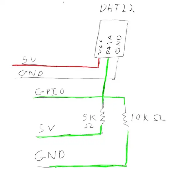
As a secondary question id like to ask about a recommendation for wiring the dht22 that was detailed in the DHT22.py library file:

For 5V operation connect pin 1 to 5V and pin 4 to ground.
The following pin 2 connection works for me.  Use at YOUR OWN RISK.

5V--5K_resistor--+--10K_resistor--Ground
                 |
DHT22 pin 2 -----+
                 |
gpio ------------+

Here is a drawing of how I understand to wire this up... Is it correct?
enter image description here

BryanK
  • 285
  • 1
  • 3
  • 8

1 Answers1

4

"I suspect that my issue could be that I am drawing too much current from the pi."

Whether or not that's the case, I'm not a fan of the "modern" practice of sourcing relatively high currents from the Pi. In all my setups, I only source power from a PSU - if not to avoid overloading then simply to avoid introducing ripple and noise in the Pi's power rail that might disturb digital signalling. Instead of sourcing from the Pi, use a 12 volt supply or a laptop PSU and get some cheap switching regulators for producing the voltages you need. Rule of thumb in case you're going to do it anyway: never go above 80% capacity in any circuit. Ever.

About the relays... Whenever you're powering coils and other inductive loads (motors, solenoids and relays being the most common examples), you're effectively creating a magnetic field that resists sudden current changes as long as the coil is powered (in practical terms, think of the powered coil as an energy storage area). When you suddenly cut the power, i.e. turn off your relay, the magnetic field collapses and this energy is converted to a huge voltage spike. This phenomenon is typically referred to as "back electromotive force" or "back-EMF" for short. Since the energy can't just disappear, it'll have to travel down the supply line where it hits your controlling circuit. This means that your NPN transistor might be taking a beating whenever you turn your relay off. Transistors and digital logic don't like that one bit!

Oscilloscope output showing the voltage spike in a solenoid being turned off: https://upload.wikimedia.org/wikipedia/commons/8/81/BackEMFWaveform.png

1

Basically your current relay setup (No back-EMF protection)

To mitigate the problem, it's common practice to add a flyback diode across the terminals of the inductive load (in parallel from GND to the positive terminal). You have to insert it so the little ring/stripe on one end of the diode is closer to the positive terminal than GND. Be careful with the orientation of the diode; put it in the wrong way and you've created a very good connection (low resistance path) from the positive to the negative terminal, also referred to as a short circuit.

2]

How it could/should look (with back-EMF protection in the form of a flyback diode. The term "flyback" only refers to the application, not the diode itself. For your low current setup, use any regular diode capable of handling hundreds of volts. Eg. a 1N4001)

Check the schematic above... Here you see a circuit with voltage spike/back-EMF protection added in the form of a diode. There's a DC power source (Vs) on the left, a coil (L1) at the top that could be your relay, a resistance (R1), a switch (SW1) and a diode (D) placed across the coil. See how the diode is "pointing towards" the positive terminal on the power supply? This means that no current can flow through it during normal DC operation. However, as soon as you turn off the relay the diode will ensure that the power stored in the coil will loop around in the coil itself until the resistance in the copper windings has "eaten up" all the energy; thus sparing your controlling circuit (SW1) from a nasty shock.

The same solenoid setup as before but this time WITH a flyback diode across the load. See that nice, horisontal line? That's safety. https://en.wikipedia.org/wiki/File:FlybackWaveform.gif

But wait, there's more!

Instead of mucking about with individual transistors and diodes, I suggest you buy 10 trusty old ULN2803 ICs for ~£1 on ebay including free shipping. (I'm not affiliated with any vendors. I simply picked the cheapest product).

The ULN2803 is a so-called Darlington transistor array. A single chip effectively gives you 8 individual NPN transistors in one small package (it actually contains 16 transistors but that's hidden away in the chip). They are perfect for your application since they have built-in flyback-diodes and each output can handle up to 500mA (~300mA when controlled from 3v3). They even have built-in input resistors of 2.7 K so you can and should connect them directly to the Pi's 3v3 GPIO.

If you get these ICs, you can safely connect up to 8 relays/motors/whatever and control them via 8 GPIO pins. Providing that all the relays are powered from an external supply - not straight from the Pi - this is a safe, cheap and stable solution. It could be done like this.

"Do you know of a way to trigger a "power cycle" for the pin without having to physically unplug the ground connection?"

Yes! Let a semiconductor do the dirty work! Simply connect GND from your sensor to one of the outputs of your newest investment - the ULN2803 :) To reset your sensor, you simply write a low/0 to the GPIO pin, wait a few seconds and then write a high/1.

jDo
  • 516
  • 2
  • 6