14

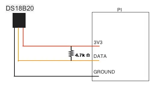
I have a raspberry pi connected to a DS18B20 temperature sensor shown in the diagram below. The one-wire software is installed and I am able to successfully read the temperature from the devices folder/file in /sys/bus/w1/devices.

enter image description here

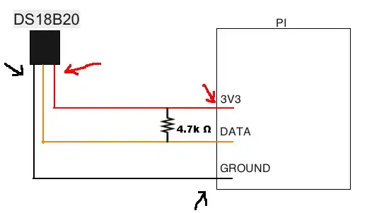
The problem I am having occurs when using much longer wire (15ft) to connect all three (ground, data, and vcc) wires from the sensor to the pi. The DS18B20 is no longer readable, there is no folder named with the serial number in the /sys/bus/w1/devices directory now. I thought I may be losing voltage due to the longer length of the wires but using a mutli-meter I am getting a 3.28V reading at the locations marked with the arrows in the next picture.

enter image description here

I am a novice and looking for help trouble shooting the issue and clarification of any apparent misconceptions I have.
BryanK
  • 285
  • 1
  • 3
  • 8

5 Answers5

6

Just solved this issue on my setup (DS18B20 worked on short cable, failed on 5M CAT3 cable, ESP8266 host). My problem was ringing; I added an 80-ohm (a semi-randomly picked low value) resistor in series with the data line at both ends of the cable, which lowered the slew rate and fixed the problem for me.

This is a very comprehensive appnote from Maxim: https://www.maximintegrated.com/en/app-notes/index.mvp/id/148/CMP/ELK5

Richard Aplin
  • 161
  • 1
  • 2
5

You could try powering the device from 5V.

You would still need to pull the data line up to 3V3 though.

joan
  • 71,852
  • 5
  • 76
  • 108
2

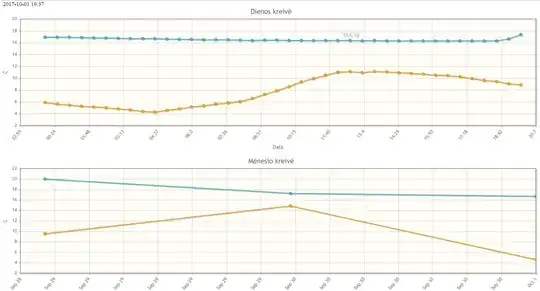
I have unshielded CAT5 cable about 40m and 7 sensors DS18B20. GROUND is connected to 2 wires from different twisted pairs, last wires from these twist pairs are used for DATA and power. Between GPIO4 and 3.3v there is a 2.2k pullup resistor and I have correct data from last 2 sensors on the wire while one sensor in the middle always shows 85000. For me it started to work when I changed pullup resistor from 4,7k tu 2.2k. Below there is a grafh of this day and all days from start enter image description here

Tadas B.
  • 21
  • 2
1

I got about 220m length with 5 Sensors. 4 in a row and the 5th is parallel to the 4th. RPi--S--S--S--S |__S I have 5V sensor voltage, 500 ohm pullup to 3.3V, Cat5e shielded cable. I think the cable really doesn't matter that much. What matters is the Pull Up. The sensors can handle about 820 ohm on the Datasheet, I use 500 Ohms only for testing Purposes. With 1kOhm i got 190m so it would be also possible to get this far with 1KOhm or 820kOhm.

With 4,7kOhm i got only about 50m or something which worried me and i never thought i can get this length. But obviously it is possible.

dgeigerd
  • 11
  • 1
0

My experiences with DS18B20 on 5V logic (comments on 3V3 below):

  • if you are using many sensors (12+) and long wires (10m+) you need to scale down the pullup resistor significantly (really drastically). I managed to make 30 thermometers work on a topology which has weight over 30-40 meters. I did not use any decupling because the problem was with slow signal rise, not with echo (as measured using oscilloscope).

  • to achieve this I had to reduce the pullup resistor to 1k ohm. Yes. 1000ohm. I was checking on oscilloscope how the signal rise gets degraded when attaching extra sensors and extra wire length. Now I have several installations with 20+ sensors each, with cables weight up to 50m and they are working.On most pictures in the internet you see the 4k7 pullup which is a joke in reality, no larger DS18B20 network will work reliably with such large pullup.

  • one comment: cable weight I am counting as the total length of all cables, plus 2m for each crossroad (star split), plus 2m for each sensor. It is not fully compliant with literature but it is working for me. In literature the cable weight calculations are sligthly different.

  • please note, that this is without using parasite power. in literature there is a schema for large networks using parasite power - search for a term 'strong pullup'. This is an extra transistor which is strongly pulling up power/data line to 5V when not transmitting/receiving data. You have to dedicate one extra microcontroller output for this, and disable strong pullup during transmission, re-enable it after transmission. I did not test it much because my networks are large (20+ thermometers) and I wanted to be on a safe side.

However now I am preparing to replace ATMEGA 5V cpus with 3.3V logic 32bit cpus. And now there is a question if anybody (except dgeigerd) has any experience with 3.3V logic for DS18B20 on larger sensor networks? Did anybody make it work, and if yes than what was the weight, and how the circuit did look like? Did anybody try anything else than powering the sensors with 5V and pulling up data line to 3V3 with small resistor like 500 ohm?

Damago
  • 1