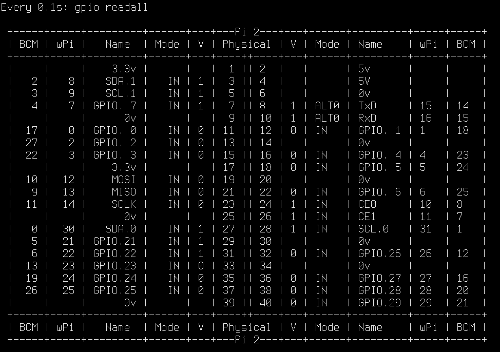
On a Rpi2, gpio readall output:
Seems completely different from this image (on elinux.org):

What am I missing?
On a Rpi2, gpio readall output:
Seems completely different from this image (on elinux.org):
What am I missing?
The table from gpio readall all is very complete and accurate. The interpretation is as follows.
Looking from the top, connector on your right, numbers are odd on the left, even on the right, the square on the PCB is pin '1'.
column 'physical'  40 pin connector position.
column 'v'         current value
column 'mode'      current mode In/Out GPIO.setup(n, GPIO.OUT)
column 'name'      human description/function
column 'wPI'       Wiring Pi (*) pin id, GPIO.setmode(GPIO.BOARD)
column 'BCM'       BCM pin Id. GPIO.setmode(GPIO.BCM)
I am not sure if this is what you are getting at but compare the elinux image with the name and physical columns in the GPIO readall output. The readall output also includes the BCM numbering scheme (the actual chip that runs the Pi) and the wiringpi (a library used to access the GPIO pins) numbering scheme. The readall output also includes the pin mode (input or output) and its current value (high 1 or low 0). This thread https://www.raspberrypi.org/forums/viewtopic.php?f=63&t=101926 contains more info on the various pin naming schemes.exactly