6

I'm building a morse transmitter. When the volume is up and I press a button it's beeping. (Also using JME8 I coded a program to get the signal from GPIO 17 and decode the morse to characters.) bad wiring

The 5V is needed to drive the buzzer (3,3 was too small for it), but the GPIO can accept 3,3V so I used a voltage divider.

When the volume control is muted and I press the button, the Raspberry restarts. What is wrong with my wiring? How can I fix it?


UPDATE:
When the potmeter is totally down and the button is pressed, a short circuit shows up between the 5V and the ground, thats why the Pi restarts.

How can I resolve a short circuit?


EDIT by SlySven: The details of the buzzer indicated that it IS a buzzer that can be driven by a constant DC supply - from the data-sheet that @SimonÁdám indicated: First page of data-sheet imageSecond page of data-sheet

However using a potentiometer to reduce the supplied current/voltage is not going to work properly to control the volume produced from all that I can see...

SlySven
  • 3,631
  • 1
  • 20
  • 46
adtewa
  • 211
  • 3
  • 9

2 Answers2

3

For starters your design is intrinsically flawed, you will have to make another implementation of what you want to do.

The explanation of why it is flawed is two fold.

  • Your potentiometer. The center tap is connected to the piezo, left to 5V and right to GND. A GND connection is unnecessary because a R in series with the piezo is enough to limit the current and make it sound lower. This GND connection is the reason why the pi is shorting out, because there is a direct path from 5V, then thru the button, then GND, this shorts out the supply and the PI browns out.
  • "Listening" on the voltage on the supply of the piezo is not a good idea. There will be voltage drops on both the piezo and the potentiometer so these readings won't be accurate if it even detected.

An easy solution would be for you to listen to your button, then switch the buzzer whenever the button is pressed.

The hardware solution would be the following:

Made using digikey's SchemeIt

The left input pin would be connected to the button. The pullup R2 can be ignored if you configure the input pin to be PULL UP.

The transistor Q1 would be a general purpose 2n2222 or the like, connected to an output pin on the raspberry. DON NOT FORGET THE RESISTANCE R1, a short on an output pin won't be as pretty as the shorts you have experienced.

All left to do is to code the modifications. If you by any means want to listen to the button being pressed, you will need to check another solution.

Working on electronics on a raspberry can be dangerous for the board. Be very careful next time

DrBomb
  • 86
  • 2
1

If you consider the circuit diagram I ran up (with gschem - part of the GPLed Electronics Design Automation project): schematic derived from diagram in question

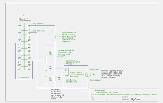
Can you see how the Potentiometer has the two Red wires in the wrong place (swap them to fix it) so that if the wiper (which SHOULD be connected to the Red wire of the Buzzer I believe) is at the bottom of its travel (near the Black wire electrically speaking, then, when the switch is pressed, it SHORTS out the 5V supply to ground.

Also, R4 is redundant as the circuit seems to be - its effects are entirely repeated by R1-3!

Also, this is only going to work so that the buzzer makes a sound when the button is pressed, if the buzzer is a device that accepts a DC voltage as a power supply and uses that to power an internal oscillator to drive the sound producing element inside. Not all "sounders" work like that, some need to be driven with an AC voltage (they do NOT have an internal oscillator circuit, they need an external one). If the buzzer is a device that takes a DC voltage and makes its own sound, then feeding the supply via a variable resistor as a potential divider is a poor design - for a good rule of thumb the amount of current that can be taken out of the middle of the divider (the wiper contact on a potentiometer) should be no more than say a fifth or better no more than a tenth of the current following from top to bottom.

A better arrangement would be to disconnect the black wire from the bottom of the variable resistor altogether and then the existing mis-wiring of the other two connections to the variable resistor is not important, so that the nearer the wiper gets to the connected end the more current/voltage/power gets through into the buzzer (and less gets lost in the variable resistor) and it should get louder as expected, depending on the relative resistances that the buzzer and the variable resistor have, you will only get any sound from the buzzer when the wiper is pretty much towards the connected end.

SlySven
  • 3,631
  • 1
  • 20
  • 46