I am using a 16x2 LCD and have it connected with MCP23017 16-bit IO port expander. To display message to the LCD, I am using Adafruit LCD library. The also have a test python code to get it working with MCP23017. I have changed the pin according to the connections I have made but it seems to be displaying only blocks in the first row of the LCD. I tried different pins, but I can't get it to work.
Adafruit library: https://github.com/adafruit/Adafruit-Raspberry-Pi-Python-Code/tree/master/Adafruit_CharLCD
Also I have I2C enabled on my Raspberry Pi 2
Code I am using:
#!/usr/bin/python
# Example script to show usage of MCP230xx GPIO extender to drive character LCD.

from Adafruit_CharLCD import Adafruit_CharLCD
from Adafruit_MCP230xx import MCP230XX_GPIO

bus = 1         # Note you need to change the bus number to 0 if running on a revision 1 Raspberry Pi.
address = 0x20  # I2C address of the MCP230xx chip.
gpio_count = 16  # Number of GPIOs exposed by the MCP230xx chip, should be 8 or 16 depending on chip.

# Create MCP230xx GPIO adapter.
mcp = MCP230XX_GPIO(bus, address, gpio_count)

# Create LCD, passing in MCP GPIO adapter.
lcd = Adafruit_CharLCD(pin_rs=0, pin_e=1, pins_db=[4,5,6,7], GPIO=mcp)

lcd.clear()
lcd.message("  Adafruit 16x2\n  Standard LCD")
Wiring:
MCP           - PI2
SCL(Pin 12)   - GIPO0 (Pin 3)
SDA(Pin 13)   - GPIO1 (Pin 5)
VDD(pin 9)    - 3.3V
VSS(Pin 10)   - Gnd
A0(Pin 15)    - Gnd
A1(Pin 16)    - Gnd
A2(Pin 17)    - Gnd
Reset(Pin 18) - 3.3V

MCP          - LCD
GPA0(Pin 21) - RS (Pin 4)
GPA1(Pin 22) - E (Pin 6)
GPA4(Pin 25) - DB4 (Pin 11)
GPA5(Pin 26) - DB5 (Pin 12)
GPA6(Pin 27) - DB6 (Pin 13)
GPA7(Pin 28) - DB7 (Pin 14)
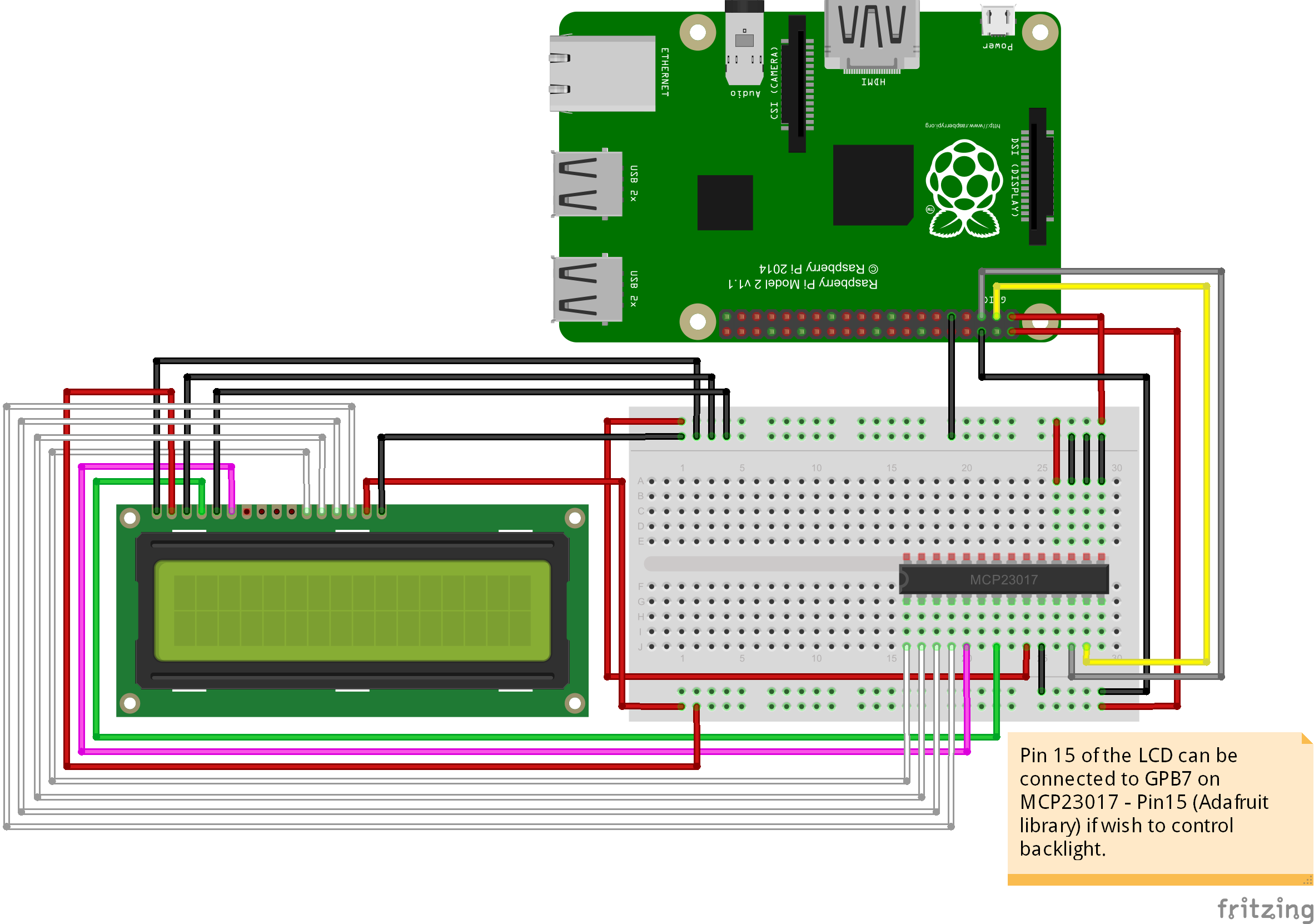
Also the RW pin of LCD is grounded. Below is the sketch for more clarity:
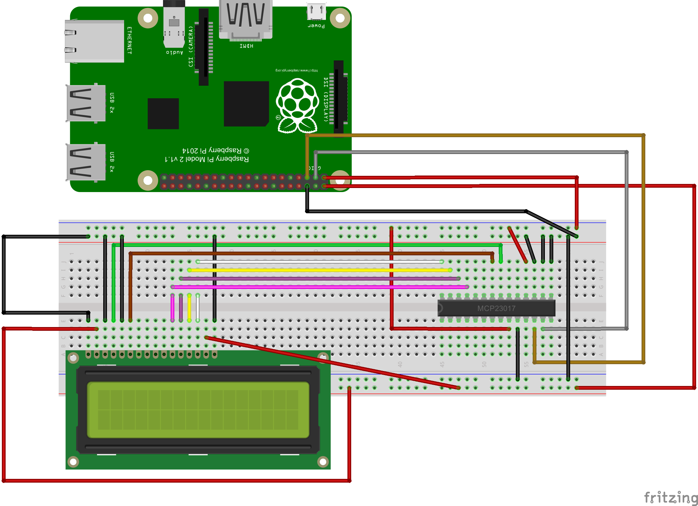
Any idea why this is happening or is there any step I am missing.