5

my current setup

I've got a single relay connected to my RPi but I can't seem to control it.

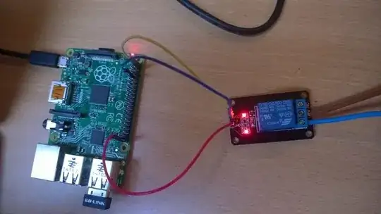
As you can see from the image above:
RPi -> Relay
5V -> VCC
Ground -> GND
GPIO4 -> IN1

Measuring voltage I can successfully verify that I can turn on/high off/low the GPIO pin (3.3V to 0V).

The problem is changing that state doesn't change the relay state. As soon as I set the pin's mode to OUT the relay lets the current go through.

Changing the pin's state through the Python API or through the console doesn't do anything, the current is always passing through. (Can turn it off by setting the pin's direction to IN..)

Also the wires connected to the relay are using NO (normally open) and COM.

Somewhere on the relay's product page it states: "Control signal TTL 3,5V-12V". Would this mean that the GPIOs output of 3.3V isn't enough to control the relay?

Steve Robillard
  • 34,988
  • 18
  • 106
  • 110

2 Answers2

1

I also came across this.

The best solution to this is that you

  • connect the gpio pin to the flyback resistor then to the Base of the transistor.
  • Ground the emitter.
  • Connect the 5v to the relay terminal and the other to the collector of the transistor.
  • Add a freewheeling diode at the terminals of the relay Yo prevent the back flow of the current.

This should solve the problem.

Bex
  • 2,929
  • 3
  • 26
  • 34
Abdeali
  • 11
  • 1
0

I have same relay. So I control it this easy:

from gpiozero import DigitalOutputDevice

relay = DigitalOutputDevice(17) # Initialize GPIO 17
relay.on() # This will turn relay on
relay.off() # This will not work :( but
relay.close() # This will turn relay off

My wiring is:

+5V -> vcc

GROUND -> gnd

GPIO17 -> in1

Relay will connect NO with COM when activated.

Eugene V
  • 1
  • 1